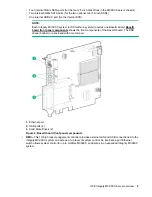


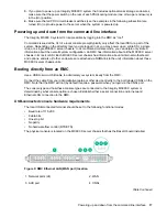


Figure 10: RMC front panel
1. Network ports (24)
2. WAN/LAN connector
3. AUX port
4. CNSL micro-USB connector
5. RST button
6. PG (Power Good) LED indicator
7. HB (Heart Beat) LED indicator
RMC overview
The RMC system for the Integrity MC990 X system manages power control and sequencing, provides
environmental control and monitoring, initiates system resets, stores identification and configuration
information, and provides console/diagnostic and scan interface.
The RMC provides the top layer of system control for the Integrity MC990 X system. This controller is a
stand-alone 1U high rack mount chassis.
NOTE:
Physical placement of the RMC is above or below the MC990 X server chassis in a rack. The RMC
slides out the front of the rack only.
The RMC uses an internal 24-port Ethernet switch, which can provide system control for up to eight
MC990 X server chassis in an expanded system. The RMC accepts direction through IPMI 2.x-enabled
protocol software and supports powering-up and powering-down individual motherboards and
environmental monitoring of all units within the MC990 X server chassis.
The RMC sends operational requests to the BMC on each compute/memory motherboard installed. The
RMC and the BMC are active whenever power is applied to the system and are not dependent on the
Integrity MC990 X system having the operating system booted and operational.
The RMC in a system distributes its inquiries and information to all the MC990 X server chassis
motherboards within the SSI.
RMC overview
23


