


3-22
Chapter 3
Gauging and Making Connections
Gauging Techniques
Gauging Techniques
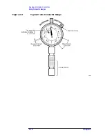
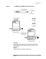
These are generic instructions for screw-on type gauges. For specific
instructions for using a 7 mm, 3.5 mm, or type-N gauge, see
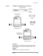
“Connecting 7 mm Gauges” on page 3-24
, and
NOTE
While performing pin depth measurements, use different orientations
of the gauge within the connector. Average a minimum of three
readings, each taken after a quarter-turn rotation of the gauge, to
reduce measurement variations that result from the gauge or the
connector face not being exactly perpendicular to the center axis.
To zero a gauge, review the instructions in
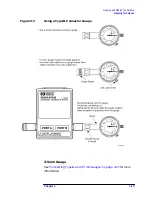
Using Male (Screw-on) Type Gauges
1. Attach the connector of the calibration module to be measured while
holding the gauge by the barrel. Tighten the nut finger-tight without
turning the gauge or calibration module.
2. Torque the connector to the appropriate torque value for the
connector supplied (see
“Torque Wrench Information” on page 2-16
3. Gently tap the barrel of the gauge with your finger to settle the
reading.
4. Measure the connector a minimum of three times, then average the
readings for maximum accuracy.
Using Female (Screw-on) Type Gauges
Screw on the connector of the calibration module to be measured while
holding the gauge by the barrel. Connect the nut finger-tight without
turning the gauge or calibration module.
5. Torque the connector using the appropriate value of torque for the
connector supplied (see
“Torque Wrench Information” on page 2-16
6. Gently tap the barrel of the gauge with your finger to settle the
reading.
7. Measure the connector a minimum of three times, then average the
readings for maximum accuracy.
Compare your averaged reading with the “Observed Pin Depth Limits”
in
through