


298
•
SPEs advertise routes permitted by routing policies to UPEs, permitting CE 1 and CE 3 in VPN
1 to communicate with each other and forbidding CE 2 and CE 4 in VPN 2 from communicating
with each other.
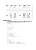
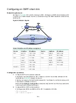
Figure 81 Network diagram
Table 22 Interface and IP address assignment
Device
Interface
IP address
Device
Interface
IP address
CE 1
GE1/1/1
10.2.1.1/24
CE 3
GE1/1/1
10.1.1.1/24
CE 2
GE1/1/1
10.4.1.1/24
CE 4
GE1/1/1
10.3.1.1/24
UPE 1
Loop0
1.1.1.9/32
UPE 2
Loop0
4.4.4.9/32
GE1/1/1
10.2.1.2/24
GE1/1/1 172.2.1.1/24
GE1/1/2
10.4.1.2/24
GE1/1/2
10.1.1.2/24
GE1/1/3
172.1.1.1/24
GE1/1/3
10.3.1.2/24
SPE 1
Loop0
2.2.2.9/32 SPE
2
Loop0 3.3.3.9/32
GE1/1/1
172.1.1.2/24
GE1/1/1
180.1.1.2/24
GE1/1/2
180.1.1.1/24
GE1/1/2
172.2.1.2/24
Configuration procedure
1.
Configure UPE 1:
# Configure basic MPLS and MPLS LDP to establish LDP LSPs.
<UPE1> system-view
[UPE1] interface loopback 0
[UPE1-LoopBack0] ip address 1.1.1.9 32
[UPE1-LoopBack0] quit
[UPE1] mpls lsr-id 1.1.1.9
[UPE1] mpls ldp
[UPE1-ldp] quit
[UPE1] interface gigabitethernet 1/1/3
[UPE1-GigabitEthernet1/1/3] ip address 172.1.1.1 24
[UPE1-GigabitEthernet1/1/3] mpls enable
[UPE1-GigabitEthernet1/1/3] mpls ldp enable
SPE 1
SPE 2
UPE 1
UPE 2
CE 1
CE 2
CE 3
CE 4
GE1/1/2
GE1/1/1
Loop0
Loop0
AS 65410
AS 65420
AS 65430
AS 65440
GE1/1/1
GE1/1/1
GE1/1/2
GE1/1/3
Loop0
Loop0
GE1/1/2
GE1/1/1
GE1/1/1
GE1/1/1
GE1/1/3
GE1/1/1
GE1/1/1
GE1/1/2
VPN 1
VPN 1
VPN 2
VPN 2
AS 100


