


140
Manual bypass tunnel for FRR configuration example
Network requirements
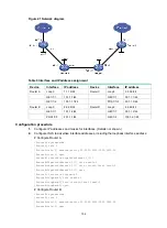
On the primary CRLSP Router A—Router B—Router C—Router D, use FRR to protect the link
Router B—Router C.
Use RSVP-TE to establish the primary CRLSP and bypass tunnel based on the constraints of the
explicit paths to transmit data between the two IP networks. The bypass tunnel uses path Router
B—Router E—Router C. Router B is the PLR and Router C is the MP.
Configure BFD for RSVP-TE between Router B and Router C. When the link between Router B and
Router C fails, BFD can detect the failure quickly and notify RSVP-TE of the failure, so RSVP-TE can
switch traffic to the bypass tunnel.
Figure 39 Network diagram
Table 7 Interface and IP address assignment
Device
Interface
IP address
Device
Interface
IP address
Router A
Loop0
1.1.1.1/32
Router B
Loop0
2.2.2.2/32
GE1/1/1
2.1.1.1/24
GE1/1/1
2.1.1.2/24
GE1/1/2
100.1.1.1/24
GE1/1/2
3.1.1.1/24
Router D
Loop0
4.4.4.4/32
POS1/1/0
3.2.1.1/24
GE1/1/1
4.1.1.2/24 Router
C
Loop0
3.3.3.3/32
GE1/1/2
100.1.2.1/24
GE1/1/1
4.1.1.1/24
Router E
Loop0
5.5.5.5/32
GE1/1/2
3.1.1.2/24
POS1/1/0
3.2.1.2/24
POS1/1/0
3.3.1.2/24
POS1/1/1
3.3.1.1/24
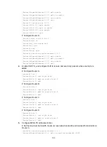
Configuration procedure
1.
Configure IP addresses and masks for interfaces. (Details not shown.)
2.
Configure IS-IS to advertise interface addresses, including the loopback interface address.
(Details not shown.)


