


37
Connecting the switch to the network
Cable routing recommendations
Interface cables and power cords should be separately routed. Reasonable cable routing can improve
efficiency by facilitating installation and removal of fan trays and some other components. Follow these
guidelines when you route the cables:
•
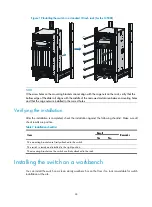
Interface cables of a 12508E and 12518E are routed through the upper and lower cable
management brackets on the chassis and bound at cabling racks on chassis sides, depending on
the available equipment room condition.
•
Put all the data signal cable adapters neatly under the chassis (instead of any places outside the
chassis in case of unexpected damages).
•
The power cords run along the left-rear of the chassis and out of the chassis either from the chassis
top or the raised floor depending on the equipment room conditions (power distribution rack,
lightning protection box, and connector strip, etc.) of the exchange office.
•
Attach cables as near the switch as possible. The cables between the fixing point and switch
interfaces must be bound loosely.
•
Long cables can be bound with cable ties. Do not bind cables at the air exhaust vent to prevent the
cables from aging too fast. For more information, see "Appendix E Cable management."
•
To identify cables, you can stick labels on them. For more information, see "Appendix F
Engineering labels for cables."
Logging in to the switch
Console port login or USB console port login, which is most commonly used, is the only method for initial
login to the switch. It is the prerequisite to configuring other login methods.
Connecting the console cable
Before login through the console port or USB console port, connect the PC (or terminal) and the switch
using the following methods accordingly:
•
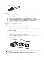
Console port
—
Use the console cable to connect the serial port on the PC (or terminal) to the console
port on the switch.
•
USB console port
—
Use the console cable to connect the USB port on the PC (or terminal) to the USB
console port on the switch.
Introduction to console cables
•
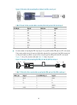
Console cables connecting the console port on a switch and serial port on a PC or terminal
The console cable is an 8-core shielded cable, with a crimped RJ-45 connector for connecting to
the console port of the switch, and a DB-9 female connector for connecting to the serial port on the
console terminal.
shows the console cable and
shows its pinouts.