background image

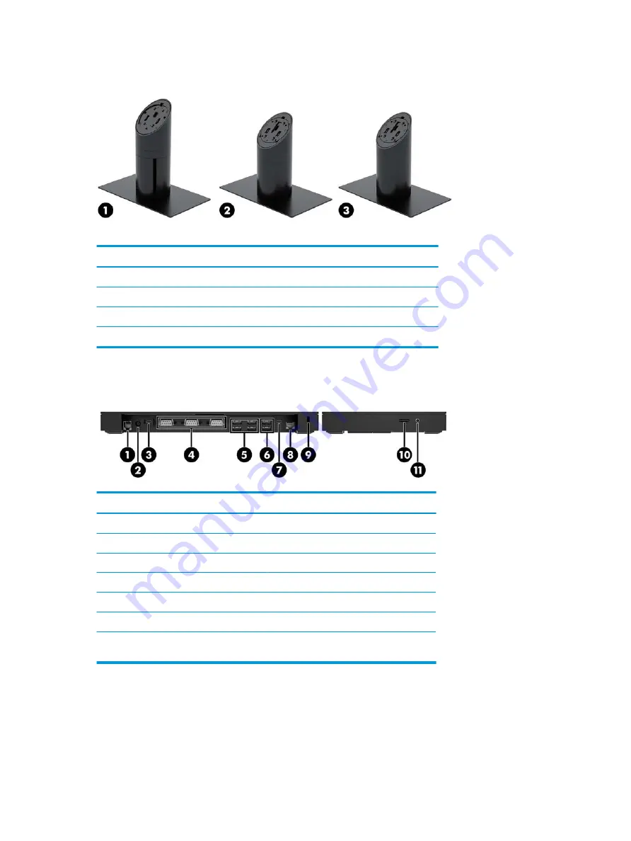
Stand options

Options

(1)

HP Engage One Rotate/Tilt Stand with Integrated Column Printer

(2)

HP Engage One Rotate/Tilt Stand

(3)

HP Engage One Fixed Position Stand

NOTE:

The stands are shown on a stability base.

HP Engage One Basic I/O Connectivity Base components

Basic components

(1)

Cash drawer jack

(7)

USB Type-C port

(2)

Power connector

(8)

RJ-45 network jack

(3)

USB Type-C power port

(9)

Security cable slot

(4)

Powered serial ports (3)

(10)

MicroSD card reader

(5)

USB 2.0 ports (4)

(11)

Headset jack

(6)

USB 3.0 ports (2)


IMPORTANT:

To avoid damage to the computer, DO NOT plug a telephone cable into the cash 

drawer jack.

4

Chapter 1   Product overview

Summary of Contents for Engage One Retail System 143

Page 1: ...Maintenance and Service Guide HP Engage One Retail System Model 141 HP Engage One Retail System Model 143 HP Engage One Retail System Model 145 ...

Page 2: ...rranty HP shall not be liable for technical or editorial errors or omissions contained herein Second Edition August 2018 First Edition August 2017 Document Part Number 925670 002 Product notice This guide describes features that are common to most models Some features may not be available on your computer Software terms By installing copying downloading or otherwise using any software product prei...

Page 3: ... another hard surface such as an adjoining optional printer or a soft surface such as pillows or rugs or clothing to block airflow Also do not allow the AC adapter to contact the skin or a soft surface such as pillows or rugs or clothing during operation The device and the AC adapter comply with the user accessible surface temperature limits defined by the International Standard for Safety of Info...

Page 4: ...iv Safety warning notice ...

Page 5: ...ed parts catalog 10 Computer major components 10 Peripherals 12 Cables and adapters 13 3 Routine care SATA drive guidelines and disassembly preparation 14 Computer operating guidelines and routine care 14 Touch screen maintenance 14 MSR maintenance 15 Service considerations 15 Tools and software requirements 15 Screws 15 Cables and connectors 15 Lithium coin cell battery 15 Electrostatic discharge...

Page 6: ...y screw on the Engage One head unit and VESA mount 35 Removing and replacing the column printer 35 Removing the display panel 41 System board components 42 Installing a 2 x 20 customer facing display CFD 43 Memory modules 45 DDR4 SDRAM SODIMMs 45 Removing a SODIMM 45 Removing and installing an M 2 solid state drive SSD 48 Removing the WLAN module 49 Removing the heat sink 51 Removing the fan assem...

Page 7: ... Retail 76 Configuring optional HP integrated peripheral modules 76 8 Computer Setup F10 Utility 77 Computer Setup F10 Utilities 77 Using Computer Setup F10 Utilities 77 Computer Setup Main 79 Computer Setup Security 81 Computer Setup Advanced 83 Recovering the Configuration Settings 87 9 POST error messages and diagnostic front panel LEDs and audible codes 88 POST numeric codes and text messages ...

Page 8: ...ry media and backups 117 Creating HP Recovery media select products only 117 Using Windows tools 119 Restore and recovery 119 Recovering using HP Recovery Manager 119 What you need to know before you get started 119 Using the HP Recovery partition select products only 120 Using HP Recovery media to recover 120 Changing the computer boot order 121 Removing the HP Recovery partition select products ...

Page 9: ...z 3M 2133 2C6 processor Model 145 anti glare WLED UWVA 500 nit panel with FHD 1920 x 1080 resolution and an Intel i5 7300U 2 60 GHZ 3MB 2133 2C6 processor NOTE Nits is the measure of the typical brightness of the panel as specified prior to anti glare coating Optional 100 mm x 100 mm VESA mounting bracket Optional counter top mounting bracket Choice of a rotate tilt stand with a 10 tilt range and ...

Page 10: ...J 45 network jack 1 video out USB Type C port HP Engage One Basic I O Connectivity Base optional 3 powered serial ports 0 V 5 V 12 V 4 USB 2 0 ports 2 USB 3 0 ports 1 cash drawer jack 1 RJ 45 network jack 1 video out USB Type C port One internal SD card reader on the computer head unit and one external microSD card reader on the I O connectivity base Universal audio jack with CTIA headset support ...

Page 11: ...ne 2 x 20 Customer facing Display CFD 2 HP Engage One Integrated Column Printer 5 HP Engage One Integrated MSR 3 Choice of 2 Engage One I O Connectivity Bases 6 HP Engage One Biometric Fingerprint Reader Display panel options Anti glare WLED SVA 300 nits panel Anti glare WLED UWVA 500 nits panel NOTE Nits is the measure of the typical brightness of the panel as specified prior to anti glare coatin...

Page 12: ...age One Basic I O Connectivity Base components Basic components 1 Cash drawer jack 7 USB Type C port 2 Power connector 8 RJ 45 network jack 3 USB Type C power port 9 Security cable slot 4 Powered serial ports 3 10 MicroSD card reader 5 USB 2 0 ports 4 11 Headset jack 6 USB 3 0 ports 2 IMPORTANT To avoid damage to the computer DO NOT plug a telephone cable into the cash drawer jack 4 Chapter 1 Prod...

Page 13: ...SB Type C port 3 Powered USB 24 V port 9 RJ 45 network jack 4 Power connector 10 Security cable slot 5 USB Type C power port 11 MicroSD card reader 6 Powered serial ports 2 12 Headset jack IMPORTANT To avoid damage to the computer DO NOT plug a telephone cable into the cash drawer jack HP Engage One Advanced I O Connectivity Base components 5 ...

Page 14: ... to the power connector on the I O connectivity base 3 To connect an AC adapter to the computer when it is not connected to an I O connectivity base connect the AC adapter to a grounded AC outlet 1 and then the connect the power adapter s USB Type C connector to the USB Type C power port on the underside of the stand or stability base 2 NOTE The image below is shown with a stability base 6 Chapter...

Page 15: ... power is not available from the I O connectivity base ports The exception is the I O connectivity base s USB Type C port that connects to the head unit That port will remain powered so that it can continue to communicate with the head unit and allow the I O connectivity base to turn back on when the head unit is turned on After the system has been turned off you can press the power button on the ...

Page 16: ...e only available on performance stands You can tilt and swivel the computer head to set it to a comfortable viewing angle There is a 10 tilt range that can be set between 50 and 60 The computer head unit can be swiveled 180 in either direction 8 Chapter 1 Product overview ...

Page 17: ...e I O connectivity base serial number location Each I O connectivity base has a unique serial number and a product ID number that are located on the exterior of the I O connectivity base Keep these numbers available for use when contacting customer service for assistance Regulatory information is located in the base plate or wall mount Install the base plate or wall mount back after disassembly En...

Page 18: ...low the on screen instructions Computer major components Item Description Whole unit not illustrated 1 Display panel Touch 500 nits Touch 300 nits 2 MSR LED board and cable 3 MSR board and cable 4 System board includes replacement thermal material Includes embedded Intel Core i5 7300U processor Includes embedded Intel Core i3 7100U processor Includes embedded Intel Celeron 3965U processor 10 Chapt...

Page 19: ...8723BE VB 802 11 bgn 1x1 Wi Fi BT4 0 Combo Adapter 10 Memory modules SODIMM DDR4 2400 16 GB 8 GB 4 GB 11 Solid state drives NVMe 1 TB TLC 512 GB PCIe 512 GB TLC PCIe 512 GB value PCIe 512 GB SATA 3 TLC 256 GB TLC PCIe 256 GB value PCIe 256 GB SATA 3 TLC 128 GB PCIe 128 GB SATA 3 TLC Power supply external 180 W 120 W 65 W USB Type C Stand fixed position Stand rotate tilt Thumb screw stand base Secu...

Page 20: ...Printer 2 HP Engage One 2D Barcode Scanner 3 HP Engage One Fingerprint Reader 4 HP Engage One Top Mount 2x20 CFD HP L8010t 10 1 Touch CFD HP L8010 10 1 Non Touch CFD 5 HP Engage One Column Printer black or white 6 I O Connectivity Base Advanced includes powered USBs Basic does not include powered USBs 12 Chapter 2 Illustrated parts catalog ...

Page 21: ...eter USB Type B to Type A Column printer cable 23 cm USB Type B to Type A Column printer cable 50 cm cash drawer 24V to Y Hosiden Type B powered USB cable for use with HP POS Hybrid Printer MICR with Imaging Module 24V powered USB cable power only Hosiden USB Type C cable coiled USB Type C cable straight USB Type C cable 20V 3A 0 43 meter USB Type C cable 20V 3A 1 8 meter USB Type C cable VESA USB...

Page 22: ...perating guidelines listed above will still apply Keep liquids away from the computer and I O connectivity base Never cover the vents on the computer or I O connectivity base with any type of material Install or enable power management functions of the operating system or other software including sleep states Turn off the computer before you do either of the following Wipe the exterior of the comp...

Page 23: ...ic threads and may be of different lengths If an incorrect screw is used during the reassembly process it can damage the unit HP strongly recommends that all screws removed during disassembly be kept with the part that was removed then returned to their proper locations CAUTION As each subassembly is removed from the computer it should be placed away from the work area to prevent damage Cables and...

Page 24: ...ile but it has been degraded in the internal layers reducing its life expectancy Networks built into many integrated circuits provide some protection but in many cases the discharge contains enough power to alter device parameters or melt silicon junctions Generating static The following table shows that Different activities generate different amounts of static electricity Static electricity incre...

Page 25: ... at standing workstations and are compatible with most types of shoes or boots On conductive floors or dissipative floor mats use them on both feet with a maximum of one megohm 10 resistance between the operator and ground Static Shielding Protection Levels Method Voltage Antistatic plastic Carbon loaded plastic Metallized laminate 1 500 7 500 15 000 Grounding the work area To prevent static damag...

Page 26: ...tations with ground cord of one megohm 10 resistance Static dissipative table or floor mats with hard tie to ground Field service kits Static awareness labels Wrist straps and footwear straps providing one megohm 10 resistance Material handling packages Conductive plastic bags Conductive plastic tubes Conductive tote boxes Opaque shielding bags Transparent metallized shielding bags Transparent shi...

Page 27: ...nitial safety procedures 1 Remove disengage any security devices that prohibit opening the computer 2 Shut down the computer properly through the operating system then turn off any external devices 3 Disconnect the power cord from the power outlet CAUTION Regardless of the power on state voltage is always present on the system board as long as the system is plugged into an active AC outlet You mus...

Page 28: ...y Preparation for disassembly on page 19 2 Remove the cover on the I O connectivity base by removing the four screws on the underside of the I O connectivity base 1 and then lifting the cover off the I O connectivity base 2 3 Connect the USB Type C power cable to the USB Type C port on the underside of the stand s column 20 Chapter 4 Removal and replacement procedures ...

Page 29: ...etween the back of the I O connectivity base and the stand 5 To connect and secure the USB Type C power cable attach the cable clip to the cable 1 insert the cable tie into the hole 2 below the USB Type C port on the hub and then slide the cable clip onto the cable tie and connect the cable to the port 3 6 Connect the I O connectivity base s AC adapter to the I O connectivity base and a grounded A...

Page 30: ...ard non powered serial ports or powered serial ports Some devices use a powered serial port If the serial port is configured as a powered port devices that support a powered serial interface do not require an external power source IMPORTANT The system must be powered off before connecting or disconnecting serial port devices NOTE The I O connectivity base ships with all serial ports configured in ...

Page 31: ... 1 that secure the bottom plate to the I O connectivity base and then remove the bottom plate from the I O connectivity base 2 3 Adjust the voltage select switch behind each serial port to the desired setting Configuring the I O connectivity base s powered serial ports 23 ...

Page 32: ...ivity base The optional fingerprint reader can be used as a standalone device or it can be attached to the I O connectivity base Follow the procedure below to connect a standalone fingerprint reader to the I O connectivity base 1 Prepare the computer for disassembly Preparation for disassembly on page 19 2 Connect the USB cable to the fingerprint reader 1 and route the cable through the routing ch...

Page 33: ...ity base NOTE You can attach the fingerprint reader to either side of the I O connectivity base but if you attach it to the left side of the I O connectivity base the fingerprint reader will cover the microSD slot and the headset jack on the I O connectivity base 1 Prepare the computer for disassembly Preparation for disassembly on page 19 2 Place the fingerprint reader 1 on the riser 2 and then a...

Page 34: ...e and then attach the bracket on the fingerprint reader assembly to the underside of the I O connectivity base 4 using the screw that was removed from the base and the short screw included in the kit 4 Connect the fingerprint reader cable to a USB Type A port on the I O connectivity base 5 Reconnect the I O connectivity base and computer power cords 26 Chapter 4 Removal and replacement procedures ...

Page 35: ...ess the release button and then pull the head unit from the stand 2 NOTE If a security screw is installed in the release hole remove the screw with a T 10 screwdriver to access the release button To attach the head unit to the stand align the guide posts on the rear of the computer head unit with the corresponding holes in the stand s column and then press the head unit onto the column Removing an...

Page 36: ...o a wall 4 Connect the USB Type C power cable to the USB Type C port on the VESA mounting bracket 1 Align the guide posts on the rear of the computer head unit with the corresponding holes in the VESA mounting bracket and then press the head unit onto the VESA mounting bracket 2 You also have the option of routing the USB Type C cable out the rear of the VESA bracket and through a wall instead of ...

Page 37: ...side of the VESA bracket through the slot on the bracket s rear cover 1 and then replace the rear cover 2 5 Connect the power cable from the VESA bracket to a wall outlet or I O connectivity base Mounting the Engage One head unit to a wall 29 ...

Page 38: ...mm to 50 mm 1 If the stand s base is attached to the column remove the screw on the underside of the column 1 and then remove the base from the column 2 2 Route the cable s through the routing hole on the top piece of the mounting bracket 1 and attach the cable s to the bottom of the column 2 NOTE If the column has a printer there are four cables to connect If it does not have a printer there is o...

Page 39: ...face Orient the bracket properly for your application before attaching it 5 Route the cables through the hole in the bottom piece of the mounting bracket 1 Press the mounting bracket against the bottom of the mounting surface 2 and then insert the screw 3 though the mounting bracket Tighten the screw 4 so that the screw is fully inserted into the column and then tighten the wing nut 5 on the screw...

Page 40: ...he I O connectivity base to a fixed object with an optional Keyed Cable lock security cable extension and an optional security cable available from HP NOTE The security cable is sold separately as an aftermarket option kit only 32 Chapter 4 Removal and replacement procedures ...

Page 41: ...from HP NOTE The security cable is sold separately as an aftermarket option kit only 1 Remove the screw from the bottom of the column 1 2 Attach the security cable extension to the bottom of the column using the tamper resistant screw 2 included with the security cable extension 3 Secure the other end of the security cable extension with a security cable 3 Installing a security cable on the Engage...

Page 42: ... screw into the computer s column with a T 10 screwdriver to prevent access to the computer head unit s release button 1 Remove the security screw from the bottom of the stand s column 2 Install the security screw in the release button hole on the stand s column 34 Chapter 4 Removal and replacement procedures ...

Page 43: ...and then install the security screw 2 in the release button hole on the VESA mount Removing and replacing the column printer 1 Prepare the computer for disassembly Preparation for disassembly on page 19 2 Remove the receipt paper from the printer 3 Disconnect the printer and system power sources and any attached devices 4 Place the computer with the display panel face down on a flat surface covere...

Page 44: ...inter base plate 1 9 Disconnect the cables from the printer and remove the cables and stand base 2 10 Rotate the column up to expose the head unit release hole 1 IMPORTANT If a security screw is installed in the release hole remove it to access the release button 36 Chapter 4 Removal and replacement procedures ...

Page 45: ...ove the two Phillips head screws with the lock washers and bushings 2 from the top and bottom of the door cover c Use a small flat head screwdriver to pry the retaining tab from behind the door cover hook 1 d Press the door cover hook out of the slot in the door frame 2 NOTE You may need to use a flat head screwdriver to help disengage the hook from the slot Removing and replacing the column print...

Page 46: ... the door frame 3 13 Close the printer door 14 Remove the four Phillips screws that secure the stand cable connector housing and then pull the cable cover away from the printer base 38 Chapter 4 Removal and replacement procedures ...

Page 47: ...ch 0 6 cm out of the column 1 17 Carefully remove the paper feed button from the opening in the column 2 18 Continue sliding the printer engine out of the column and remove 3 To replace the column printer reverse the removal procedures Please note the following tips when replacing the column printer Remove the alignment pin from the bottom of printer engine Removing and replacing the column printe...

Page 48: ... printer engine into the column until the actuator arm is visible through hole 2 With the alignment stud oriented toward the top of the column place the paper feed button into the opening in the column 1 Continue sliding the printer engine into the column until the button is fully engaged and the engine is fully seated 2 40 Chapter 4 Removal and replacement procedures ...

Page 49: ...ay panel up approximately 2 5 cm one inch IMPORTANT Do not lift the display panel higher than 2 5 cm one inch from the computer head unit An internal cable must be disconnected before the display panel can be fully removed 5 Holding the display panel 2 5 cm one inch from the computer head unit shift the display panel forward no more than 7 5 cm three inches 1 to access the display cable connection...

Page 50: ...ing the display panel so that the cables do not become disconnected 7 Disconnect the touch cable from the system board and the WLAN antennas from the WLAN module To replace the display panel reverse the removal procedures System board components Refer to the table below to locate the system board components referenced in this guide System board components 1 SD card slot 4 WLAN module 2 CFD connect...

Page 51: ...3 Remove the display panel from the computer head unit Removing the display panel on page 41 4 Remove the rubber stoppers from the CFD cable routing channel and the two CFD screw holes 5 Route the CFD cable through the routing channel on the computer head unit 1 Pull the cable all the way through the channel 2 and then slide the screw tabs on the CFD into the slots on the computer head unit 3 Inst...

Page 52: ...through the head unit routing channel before installing the CFD so that the cable does not get pinched between the CFD and the head unit 7 Replace the computer head unit s display panel 8 Attach the computer head unit to the stand See Removing and attaching the Engage One head unit to the stand on page 27 9 Reconnect the power cord and press the power button 44 Chapter 4 Removal and replacement pr...

Page 53: ...400 SODIMM memory NOTE The system will not operate properly if you install unsupported SODIMMs Removing a SODIMM CAUTION You must disconnect the power cord and wait approximately 30 seconds for the power to drain before replacing the memory module Regardless of the power on state voltage is always supplied to the memory module as long as the computer is plugged into an active AC outlet Adding or r...

Page 54: ... display panel from the computer head unit Removing the display panel on page 41 4 Remove the shield over the memory modules by pulling the tab on the shield up 1 and then lifting the shield from the system board 2 5 To remove a memory module press outward on the two latches on each side of the memory module 1 and then pull the memory module out of the socket 2 46 Chapter 4 Removal and replacement...

Page 55: ... place NOTE A memory module can be installed in only one way Match the notch on the module with the tab on the memory socket 7 Replace the shield over the memory modules by pressing the left side of the shield down onto the system board 1 and then the pressing the right side down 2 The computer automatically recognizes the additional memory when you turn on the computer Memory modules 47 ...

Page 56: ...nit from the stand Removing and attaching the Engage One head unit to the stand on page 27 3 Remove the display panel from the computer head unit Removing the display panel on page 41 4 To remove an SSD remove the screw that secures the SSD to the system board 1 and then slide the SSD out of the system board connector 2 5 To install an SSD slide the connector end of the SSD into the system board c...

Page 57: ... the stand Removing and attaching the Engage One head unit to the stand on page 27 3 Remove the display panel from the computer head unit Removing the display panel on page 41 4 To remove a WLAN module disconnect the WLAN cables 1 remove the screw 2 that secures the module to the system board and then slide the module out of the system board connector 3 IMPORTANT The WLAN cables and connectors are...

Page 58: ...hen connect the two cables from the display panel to the connectors on the WLAN module 3 IMPORTANT The WLAN cables and connectors are labeled 1 and 2 Make sure that you match the numbered labels on the WLAN module with the numbered labels on the cables when connecting the cables To install a WLAN module reverse the removal procedures 50 Chapter 4 Removal and replacement procedures ...

Page 59: ... on page 27 3 Remove the display panel from the computer head unit Removing the display panel on page 41 4 In the order indicated on the heat sink loosen the five captive Phillips screws that secure the heat sink to the system board 1 5 5 Lift the heat sink off the system board 6 CAUTION To reduce a degradation in thermal performance be sure not to touch the thermal grease on the surface of the pr...

Page 60: ...and on page 27 3 Remove the display panel from the computer head unit Removing the display panel on page 41 4 Disconnect the fan cable from the system board 1 and then remove the tape that secures the cable to the system board 2 5 Loosen the four captive Phillips screws 3 that secure the fan assembly to the computer head unit 6 Remove the fan assembly from the computer head unit 4 To reinstall the...

Page 61: ...e the computer head unit from the stand Removing and attaching the Engage One head unit to the stand on page 27 3 Remove the display panel from the computer head unit Removing the display panel on page 41 4 For each speaker disconnect the cable from the system board 1 and then use a flat tool to pry each speaker out of the computer head unit 2 The speakers are held in place with adhesive To replac...

Page 62: ... unit to the stand on page 27 3 Remove the display panel from the computer head unit Removing the display panel on page 41 4 Disconnect the cable from the system board ZIF connector 1 and then lift the cable up to disengage it from the adhesive that secures the cable to the system board 5 Remove the Phillips screw 2 6 Lift the power button board out of the computer head unit 3 To reinstall the pow...

Page 63: ...it to the stand on page 27 3 Remove the display panel from the computer head unit Removing the display panel on page 41 4 Remove the top screw 1 and bracket 2 and then remove the bottom Phillips screw 3 and bracket 4 from the reader 5 Disconnect the MSR board cable from the system board 1 TIP Take extra care when disconnecting the cable Pulling on the cable prematurely before it is disconnected co...

Page 64: ...MSR hardware and loaded its drivers successfully 2 Test the MSR to ensure it is reading magnetic data as follows a Make sure the device is in USB HID KBD mode default for the MSR b Open Microsoft Notepad and swipe a credit card c Verify that data appears in Notepad the data will be unreadable If nothing appears in Notepad confirm that the MSR is in USB HID KB mode Testing the MSR in USG HID mode T...

Page 65: ...Facility KIF NOTE Injecting the key using RKI can only be performed by the company named ID Tech ID Tech provides the necessary forms procedures tools information and timelines 1 Contact ID Tech which will provide a Windows based computer remote key loading software application The software can run independently or be integrated within the business application 2 The Remote Key Loading software com...

Page 66: ... 27 3 Remove the display panel from the computer head unit Removing the display panel on page 41 4 Disconnect the cable from the system board 1 TIP Take extra care when disconnecting the cable Pulling on the cable prematurely before it is disconnected could cause damage to the connector 5 Remove the Phillips screw 2 that secures the board to the computer head unit 6 Remove the board and cable asse...

Page 67: ...nd on page 27 3 Remove the display panel from the computer head unit Removing the display panel on page 41 4 Remove the heat sink Removing the heat sink on page 51 5 Remove the power button board Removing the power button board on page 54 6 When replacing the system board make sure the following components are removed from the defective system board and installed on the replacement system board Me...

Page 68: ...ker 7 Fan assembly 10 Remove the 6 Phillips screws that secure the system board to the computer head unit 1 11 Remove the system board from the computer head unit 2 To install the system board reverse the removal procedures NOTE When replacing the system board you must change the chassis serial number in the BIOS 60 Chapter 4 Removal and replacement procedures ...

Page 69: ...rd CMOS Yellow Reset CMOS P71 Black Power button board CPU FAN Black Fan assembly SSD Black Solid state drive DIMM1 Black Memory module SPKR_L Black Speaker DIMM3 Black Memory module SPKR_R Black Speaker eDP Silver Display connector TOUCH White Touch board MSR Black MSR board WLAN Black WLAN module Removing the system board 61 ...

Page 70: ...attaching the Engage One head unit to the stand on page 27 3 Remove the display panel from the computer head unit Removing the display panel on page 41 4 Position the display panel upside down 5 Peel the foam off the top of the display panel 6 Peel the antennas off the top of the display panel 1 and the remove the cables from the routing paths along the top of the display 2 To reinstall the antenn...

Page 71: ...Kanji 949 Korean 936 Simplified Chinese and 950 Traditional Chinese Integrated bar codes Code 39 Code 93 Code 128 UPC A UPC E JAN8 EAN JAN13 EAN Interleaved 2 of 5 Codabar Code 128 PDF 417 two dimensional Code 128 extended GS1 Databar QR code and Datamatrix Print Monochrome in either 44 standard or 56 compressed columns on 80 mm wide thermal paper Paper path 80 0 mm Roll Diameter 50 8 mm max 2 inc...

Page 72: ...the printer runs out of paper The printer may continue to accept data from the host computer even though it is unable to print Data may be lost as a result Loading the printer receipt paper 1 Open the receipt cover by pushing up evenly on each side of the cover until it unsnaps 1 2 Remove the test printout or used paper roll if necessary 3 Place the receipt paper into the paper compartment on the ...

Page 73: ...er of 22 0 5 mm 0 87 outside and 11 5 0 5 mm 0 45 inside Qualified paper grades Contact the manufacturer of your choice to order paper HP recommends the following paper grades produced by their respective manufacturers There are a number of paper manufacturers qualified to provide this paper provided the POS paper rolls are from the recommended grades for monochrome black ink paper Qualified manuf...

Page 74: ...itsubishi Int l Corp USA 655 Third Ave New York New York 10017 http www mitsubishicorp com us en Voice 212 605 2000 Fax 212 605 2597 P 5035 T 8051 TP 8065 PP 5051 OJI Paper Company Ltd Ginza 4 chome Tokyo 104 Japan http www ojipaper co jp english Voice 81 3 3563 1111 Fax 81 3 3563 1135 KF 60 PD 170R PD 170R Thermal Solutions Intl Inc 6740 Broadview Ave Suite D Jacksonville FL 32254 http thermalsol...

Page 75: ...ses Possible solutions Where to go for more information Colored stripe on the receipt Paper is low Change the paper See Loading the printer receipt paper on page 64 Receipt does not come out all the way Paper is jammed Open the receipt cover inspect the knife and clear any jammed paper Printer starts to print but stops while the receipt is being printed Paper is jammed Open the receipt cover inspe...

Page 76: ...ossible solutions Where to go for more information Printer does not function when turned on and LED is off Power is not plugged in Check that the host or power supply is getting power Printer does not function when turned on and LED is blinking Receipt cover is not fully closed Close and latch the receipt cover Printer stops functioning Printhead has overheated Allow the printhead to cool down Pri...

Page 77: ...eceipt cover should open Cleaning the printer Because of the way the printer sits while in use it is likely there will be buildup of paper and other debris from the knife HP recommends that you keep the printer in working order by periodically cleaning the debris from the printer To clean the printer open the cover remove the paper roll and then use a can of compressed air to blow the debris out f...

Page 78: ...printer AC power cord 5 I O connectivity base mini USB Type B to USB Type A data cable 2 Column printer AC adapter cable 6 I O connectivity base USB Type C cable 3 Cash drawer cable purchased separately with cash drawer 7 I O connectivity base 120 W AC power cord 4 Column printer cash drawer cable 70 Chapter 6 Cable routing configurations ...

Page 79: ...ctivity base 180 W AC power cord 4 Column printer 24 V PUSB power and data Y cable 2 Cash drawer cable purchased separately with cash drawer 5 I O connectivity base USB Type C cable 3 Column printer cash drawer cable Cable matrix for Engage One with integrated column printer and advanced I O connectivity base 71 ...

Page 80: ...Cable matrix for Engage One without I O connectivity base Cables 1 PC power cord 72 Chapter 6 Cable routing configurations ...

Page 81: ...I O connectivity base USB Type C cable 5 USB C mini dock captive USB Type C cable 3 Advanced I O connectivity base 180 W AC power cord NOTE In the European region the USB C mini dock is sold as an aftermarket option kit only In all other regions the USB C mini dock is sold as drop in box option Cable matrix for Engage One with I O connectivity base 73 ...

Page 82: ...to Type B data cable 2 Basic I O connectivity base 120 W AC power cord 5 Basic I O connectivity base USB Type C cable 3 Printer serial data cable IMPORTANT Connect either the serial data cable 3 or the USB Type A data cable 4 between the I O connectivity base and the printer Do not connect both 74 Chapter 6 Cable routing configurations ...

Page 83: ...se 180 W AC power adapter cord 5 Advanced I O connectivity base USB Type C cable 3 Printer 24 V PUSB power cable IMPORTANT Connect either the 24 V PUSB power and data Y cable 1 or the 24 V PUSB power cable 3 and serial data cable 4 between the I O connectivity base and the printer Do not connect all three Cable matrix for Engage One with advanced I O connectivity base and standalone printer 75 ...

Page 84: ...PC Settings dialog box tap the Calibrate button and then proceed to step 3 3 Follow the on screen instructions to press the target marks on the touch screen At the end of the calibration process the touch module should be aligned with the video and the touch points will be accurate Configuring optional HP integrated peripheral modules To configure the integrated USB peripheral refer to the HP Poin...

Page 85: ...stablish a setup password that controls access to the Computer Setup F10 Utility and the settings described in this section Secure integrated I O functionality including the serial USB or parallel ports audio or embedded NIC so that they cannot be used until they are unsecured Enable or disable removable media boot ability Solve system configuration errors detected but not automatically fixed duri...

Page 86: ...menu press Esc 5 To apply and save changes select Main Save Changes and Exit If you have made changes that you do not want applied select Ignore Changes and Exit To reset to factory settings or previously saved default settings some models select Apply Factory Defaults and Exit This option will restore the original factory system defaults NOTE Not all settings shown in the following sections are a...

Page 87: ...icroCode Revision Processor Stepping Memory Speed DIMM 1 Size DIMM 3 Size System BIOS version ME Firmware Version Reference Code Revision Video BIOS Version Super I O Firmware Version USB Type C Controller s Firmware Version Born On Date Serial Number SKU number UUID Universally Unique Identifier Asset Tracking Number Feature Byte Build ID Product Family System Board ID System Board CT System Diag...

Page 88: ...Settings Lets you configure upload and download settings Proxy Server select to enable use of a proxy server Edit Proxy Server If Proxy Server is enabled lets you specify the server address in server port format Test Network Connection select to check the network connection based on the selection in Automatic BIOS Update Setting IPv4 Configuration select Automatic or Manual If Manual is selected y...

Page 89: ... on screen if the computer is capable of booting this far If the POST detects an error before this point a beep code is generated instead Computer Setup Security NOTE Support for specific Computer Setup options may vary depending on the hardware configuration Table 8 2 Computer Setup Security Option Description Create BIOS Administrator Password Lets you set and enable a BIOS administrator passwor...

Page 90: ...en tampered with before the host CPU executes that code as part of the process of resuming from the low power state Enabled When this box is checked the HP Sure Start will continue to verify the integrity of the BIOS in System Flash each time the system is in a Sleep Hibernate or Off state Additionally the HP Sure Start will verify the integrity of the BIOS in System Flash on each Warm Boot Window...

Page 91: ...Once a hard drive has been erased with a program that utilizes Secure Erase firmware commands no file recovery program partition recovery program or other data recovery method will be able to extract data from the drive System Management Command Allows authorized personnel to reset security settings during a service event Default is enabled Restore Security Settings to Default Restoring settings t...

Page 92: ...ve priority in the boot sequence and will be recognized as drive C if any devices are attached NOTE To drag a device to a preferred place press Enter To remove the device from consideration as a bootable device press F5 You can use F5 to disable individual boot items as well as disable UEFI boot and or legacy boot NOTE MS DOS drive lettering assignments may not apply after a non MS DOS operating s...

Page 93: ...bled M 2 SSD Select to show the device in the operating system Default is enabled Allow PCIe PCI SERR Interrupt Allows PCI devices to report PCI PCIe System Error signals such as address parity errors data parity errors and critical errors other than parity Default is enabled Power Button Override disable 4 sec 15 sec Lets you disable or enable and select the number of seconds you have to hold dow...

Page 94: ... Port 3 USB 2 0 Port 4 USB 2 0 Port 5 USB 2 0 Port 6 SATA0 SATA1 SATA4 Bottom USB Type C port Media card reader Cash Drawer Port USB Type C Controller Firmware Update Option ROM Launch Policy These policies control whether the Legacy Option ROM or the UEFI driver is loaded Default is All UEFI Configure Option ROM Launch Policy All legacy All UEFI All UEFI except video Power Management Options Runt...

Page 95: ... shutdown goes to the S4 state S0 On Solid white LED S3 Stand By 3 blinks at 1Hz 50 duty cycle followed by a pause of 2 seconds white LED repeated cycles of 3 blinks and a pause S4 Hibernation 4 blinks at 1Hz 50 duty cycle followed by a pause of 2 seconds white LED repeated cycles of 4 blinks and a pause S5 Soft Off LED is off Recovering the Configuration Settings This method of recovery requires ...

Page 96: ...chedule reconfigure the computer to the Full Boot Every x Days mode using Computer Setup NOTE For more information on Computer Setup see Computer Setup F10 Utility on page 77 POST numeric codes and text messages This section covers those POST errors that have numeric codes associated with them The section also includes some text messages that may be encountered during POST NOTE The computer will b...

Page 97: ...tup to update this information 00B MEBx Module did not checksum correctly Memory error during POST execution of the Management Engine ME BIOS Extensions option ROM 1 Reboot the computer 2 Unplug the power cord re seat the memory modules and reboot the computer 3 If the memory configuration was recently changed unplug the power cord restore the original memory configuration and reboot the computer ...

Page 98: ...odule in Memory Socket s X X A memory module in memory socket identified in the error message is missing critical SPD information or is incompatible with the chipset 1 Verify proper memory module type 2 Try another memory socket 3 Replace with a supported module 2E4 DIMM Configuration Warning The current memory configuration is not optimized Rearrange the DIMMs so that each channel has the same am...

Page 99: ...urity and resetting CMOS on page 95 3 Replace the hard disk drive 3F2 Hard Disk 2 Error Hard disk 2 error 1 Check and or replace cables 2 Clear CMOS See Password security and resetting CMOS on page 95 3 Replace the hard disk drive 400 Serial Port A Address Conflict Detected Both external and internal serial ports are assigned to the same resources 1 Remove any serial port expansion cards 2 Clear C...

Page 100: ... be very low For optimal performance replace the battery 70x Wireless Mode Not Supported The system has detected a wireless module installed in the system that is not supported and has been disabled Replace with a supported module 800 Keyboard Error Keyboard failure 1 Reconnect keyboard with computer turned off 2 Check connector for bent or missing pins 3 Ensure that none of the keys are depressed...

Page 101: ...tioned 1 Reseat power supply fan 2 Reseat fan cable 3 Replace power supply fan Interpreting system validation diagnostic front panel LEDs and audible codes During the system validation phase that occurs at system startup the BIOS validates the functionality of the following subsystems and conditions AC adapter System board power Processor failure BIOS corruption Memory failure Graphics failure Sys...

Page 102: ... embedded controller is checking or recovering the boot block Hardware 3 2 The embedded controller has timed out waiting for BIOS to return from memory initialization 3 3 The embedded controller has timed out waiting for BIOS to return from graphics initialization 3 4 The system board displays a power failure crowbar 3 5 The processor is not detected 3 6 The processor does not support an enabled f...

Page 103: ...on the computer by resetting the password jumper CAUTION Pushing the CMOS button will reset CMOS values to factory defaults It is important to back up the computer CMOS settings before resetting them in case they are needed later Back up is easily done through Computer Setup See Computer Setup F10 Utility on page 77 for information on backing up the CMOS settings Resetting the password jumper CAUT...

Page 104: ...d jumper is blue so that it can be easily identified For assistance locating the password jumper and other system board components see the system board components image at Removing the system board on page 59 5 Remove the jumper from pins 1 and 2 6 Place the jumper on either pin 1 or 2 but not both so that it does not get lost 7 Replace the access panel and reconnect the external equipment 8 Plug ...

Page 105: ...new password again as shown current password 4 Press Enter Clearing and resetting the CMOS The computer s configuration memory CMOS stores information about the computer s configuration The CMOS button resets CMOS but does not clear the power on and setup passwords 1 Turn off the computer and any external devices and disconnect the power cord from the power outlet 2 Disconnect external equipment c...

Page 106: ...MOS button will not clear CMOS if the power cord is connected NOTE For assistance locating the CMOS button and other system board components see the system board components image at Removing the system board on page 59 5 Replace the access panel 6 Reconnect the external devices 7 Plug in the computer and turn on power NOTE You will receive POST error messages after clearing CMOS and rebooting advi...

Page 107: ...nnected USB drive NOTE To download the HP PC Hardware Diagnostics UEFI tool to a USB drive see Downloading HP PC Hardware Diagnostics UEFI to a USB device on page 99 b Hard drive c BIOS 3 When the diagnostic tool opens select the type of diagnostic test you want to run and then follow the on screen instructions NOTE If you need to stop a diagnostic test press esc Downloading HP PC Hardware Diagnos...

Page 108: ... access to the tools from the HP website or from a server that has been preconfigured for use Your computer does not require the traditional local storage such as a disk drive or USB flash drive to run remote diagnostics Set a location for storing the test results You can also set the user name and password settings used for uploads Display status information about the diagnostics run previously C...

Page 109: ...Setup Refer to Computer Setup F10 Utility on page 77 for more information Check the Power LED on the front of the computer to see if it is flashing red The flashing lights are error codes that will help you diagnose the problem Refer to POST error messages and diagnostic front panel LEDs and audible codes on page 88 for more information If the screen is blank plug the monitor into a different vide...

Page 110: ...lugged into a working electrical outlet Check that the voltage select switch some models is set to the appropriate voltage for your region 115V or 230V Check that the computer is turned on and the white power light is on Check that the monitor is turned on and the green monitor light is on Check the Power LED on the front of the computer to see if it is flashing red The flashing lights are error c...

Page 111: ...stem specific problems The issues listed in this section are specific to features available in this retail system IMPORTANT Always be sure to load the latest BIOS and drivers available from http support hp com Powered serial ports do not have power Cause Solution Ports are not correctly configured The serial ports can be configured as standard non powered serial ports or powered serial ports To ch...

Page 112: ...being replaced 2 Start HP magnetic stripe reader configuration utility http h20564 www2 hp com hpsc swd public detail swItemId ir_125989_1 swEnvOid 4047 3 Retrieve the configuration details from the old MSR and save 4 Connect the new MSR the replacement 5 Write the saved configuration to the new MSR Solving general problems You may be able to easily resolve the general problems described in this s...

Page 113: ...rt computer Computer date and time display is incorrect Cause Solution RTC real time clock battery may need to be replaced NOTE Connecting the computer to a live AC outlet prolongs the life of the RTC battery Reset the date and time under Control Panel Computer Setup can also be used to update the RTC date and time If the problem persists replace the RTC battery See the Removal and Replacement sec...

Page 114: ...nnected and working properly some fans only operate when needed 3 Make sure the processor heat sink is installed properly Hard drive is full Transfer data from the hard drive to create more space on the hard drive Low on memory Add more memory Hard drive fragmented Defragment hard drive Program previously accessed did not release reserved memory back to the system Restart the computer Virus reside...

Page 115: ...onto the system board header 3 If fan a plugged in and not spinning replace it System does not power on and the LEDs on the front of the computer are not flashing Cause Solution System unable to power on Press and hold the power button for less than 4 seconds If the hard drive LED turns white then 1 If equipped with a voltage selector check that the voltage selector located on the rear of the powe...

Page 116: ...nter port is the address of the printer being used If the printer works reload the printer driver To run MS DOS commands press the Windows key r type cmd in the Open box and then click OK If you are on a network you may not have made the connection to the printer Make the proper network connections to the printer Printer may have failed Run printer self test Printer will not turn on Cause Solution...

Page 117: ...urely connected and that pins in the cable or connector are not bent down Power switch of new external device is not turned on Turn off the computer turn on the external device then turn on the computer to integrate the device with the computer system When the system advised you of changes to the configuration you did not accept them Reboot the computer and follow the instructions for accepting th...

Page 118: ...ems Some common causes and solutions for network problems are listed in the following table These guidelines do not discuss the process of debugging the network cabling Network driver does not detect network controller Cause Solution Network controller is disabled 1 Run Computer Setup and enable network controller 2 Enable the network controller in the operating system using Device Manager To acce...

Page 119: ...n The cable is not securely connected Ensure that the cable is securely attached to the network connector and that the other end of the cable is securely attached to the correct device The cable is attached to the incorrect connector Ensure that the cable is attached to the correct connector There is a problem with the cable or a device at the other end of the cable Ensure that the cable and devic...

Page 120: ...annot connect to network server when attempting Remote System Installation Cause Solution The network controller is not configured properly Verify Network Connectivity that a DHCP Server is present and that the Remote System Installation Server contains the NIC drivers for your NIC System setup utility reports unprogrammed EEPROM Cause Solution Unprogrammed EEPROM Contact an authorized service pro...

Page 121: ...e Solution You have run out of memory to run the application Check the application documentation to determine the memory requirements Memory count during POST is wrong Cause Solution The memory modules may not be installed correctly Check that the memory modules have been installed correctly and that proper modules are used Integrated graphics may use system memory No action required Insufficient ...

Page 122: ... Media Boot is disabled in the Computer Setup utility Run the Computer Setup utility and enable booting to removable media in Advanced Boot Options Ensure USB is enabled in Storage Boot Order The computer boots to DOS after making a bootable flash drive Cause Solution Flash drive is bootable Install the flash drive only after the operating system boots Flash drive is defective Try a different flas...

Page 123: ... your ISP for the correct IP address Cookies are corrupted A cookie is a small piece of information that a Web server can store temporarily with the Web browser This is useful for having the browser remember some specific information that the Web server can later retrieve Windows 10 1 Type control panel in the taskbar search box and then select Control Panel from the list of applications 2 Click I...

Page 124: ...l not continue and the HP logo does not display Cause Solution ROM issue POST error has occurred Observe the beeps and LED lights on the front of the computer See POST error messages and diagnostic front panel LEDs and audible codes on page 88 to determine possible causes See the Worldwide Limited Warranty for terms and conditions Illegal Operation has Occurred error message is displayed Cause Sol...

Page 125: ...al information For more information see Using Windows tools on page 119 NOTE If storage is 32 GB or less Microsoft System Restore is disabled by default Creating HP Recovery media select products only If possible check for the presence of the Recovery partition and the Windows partition From the Start menu select File Explorer If your computer does not list the Windows partition and the Recovery p...

Page 126: ...he computer the drive cannot be connected to a USB port on an external device such as a USB hub If you cannot create DVD media yourself you can obtain recovery discs for your computer from HP See the Worldwide Telephone Numbers booklet included with the computer You can also find contact information on the HP website Go to http www hp com support select your country or region and follow the on scr...

Page 127: ...n select products only or use the HP Recovery media For more information see Recovering using HP Recovery Manager on page 119 If you have not already created recovery media see Creating HP Recovery media select products only on page 117 On select products if you want to recover the computer s original factory partition and content or if you have replaced the hard drive you can use the Factory Rese...

Page 128: ...re installed at the factory Factory Reset Restores the computer to its original factory state by deleting all information from the hard drive and re creating the partitions Then it reinstalls the operating system and the software that was installed at the factory The HP Recovery partition select products only allows System Recovery only Using the HP Recovery partition select products only The HP R...

Page 129: ... select products only HP Recovery Manager software allows you to remove the HP Recovery partition to free up hard drive space IMPORTANT After you remove the HP Recovery partition you will not be able to perform System Recovery or create HP recovery media from the HP Recovery partition So before you remove the Recovery partition create HP Recovery media see Creating HP Recovery media select product...

Page 130: ...cy responsible for evaluation in the country where the power cord set will be installed 2 The power cord set must have a minimum current capacity of 10A 7A Japan only and a nominal voltage rating of 125 or 250 volts AC as required by each country s power system 3 The diameter of the wire must be a minimum of 0 75 mm2 or 18AWG and the length of the cord must be between 1 8 m 6 feet and 3 6 m 12 fee...

Page 131: ... set fittings appliance coupler and wall plug must bear the certification mark of the agency responsible for evaluation in the country where it will be used 2 The flexible cord must be Type SVT or equivalent No 18 AWG 3 conductor The wall plug must be a two pole grounding type with a NEMA 5 15P 15A 125V or NEMA 6 15P 15A 250V configuration 3 Appliance coupler flexible cord and wall plug must bear ...

Page 132: ...beginning steps in this chapter Current BIOS steps 1 Follow steps a through l below to restore the nonvolatile memory that can contain personal data Restoring or reprogramming nonvolatile memory that does not store personal data is neither necessary nor recommended a Turn on or restart the computer and then press esc while the Press the ESC key for Startup Menu message is displayed at the bottom o...

Page 133: ...tform Module TPM and or fingerprint reader one or two prompts will appear one to clear the TPM and the other to Reset Fingerprint Sensor press or tap F1 to accept or F2 to reject l Remove all power and system batteries for at least 24 hours 2 Complete one of the following Remove and retain the storage drive or Clear the drive contents by using a third party utility designed to erase data from an S...

Page 134: ...4 KBytes not customer accessible No Yes Stores NIC configuration and NIC firmware NIC EEPROM is programmed using a utility from the NIC vendor that can be run from DOS A utility is required to write data to this memory and is available from the NIC vendor Writing data to this ROM in an inappropriate manner will render the NIC non functional DIMM Serial Presence Detect SPD configuration data 256 By...

Page 135: ...pplied using this utility Bluetooth flash select products only 2 Mbit No Yes Stores Bluetooth configuration and firmware Bluetooth flash is programmed at the factory Tools for writing data to this memory are not publicly available but can be obtained from the silicon vendor A utility is required for writing data to this memory and is made available through newer versions of the driver whenever the...

Page 136: ...diagnostics The UEFI BIOS provides functionality beyond that of the legacy BIOS In addition the UEFI BIOS works to initialize the computer s hardware before loading and executing the OS the run time environment allows the loading and execution of software programs from storage devices to provide more functionality such as advanced hardware diagnostics with the ability to display more detailed syst...

Page 137: ...oot Keys a Turn on or restart the computer and then press esc while the Press the ESC key for Startup Menu message is displayed at the bottom of the screen b Select the Security menu select Secure Boot Configuration and then follow the on screen instructions c At the Secure Boot Configuration window select Secure Boot select Clear Secure Boot Keys and then follow the on screen instructions to cont...

Page 138: ... 162 0 mm 29 2 mm 0 6 kg 11 2 in 6 4 in 1 1 in 1 3 lbs Display Head Unit with collar without stand Weight 1 4 kg 3 1 lbs Rotate Tilt Stand Weight 1 3 kg 3 0 lbs Fixed Position Stand Weight 1 1 kg 2 4 lbs Temperature Range Operating Nonoperating 50 to 95 F 22 to 140 F 10 to 35 C 30 to 60 C Relative Humidity noncondensing Operating 20 85 20 85 Maximum Altitude unpressurized Operating Nonoperating 10...

Page 139: ... CE mark requirements for use in the countries of the European Union The active power factor corrected power supply also has the added benefit of not requiring an input voltage range select switch 2 High efficiency power supply is a requirement for ENERGY STAR qualification in conjunction with a select range of processors and modules 131 ...

Page 140: ... F10 Setup access problem 104 fan removal and replacement 52 fan assembly illustrated 11 features 1 3 fingerprint reader attaching to base 25 connecting as standalone 24 flash drive problems 114 flashing LEDs 93 G general problems 104 grounding methods 17 H hardware installation problems 109 head unit adjustment 8 head unit security screw with stand 34 with VESA mount 35 heat sink illustrated 11 r...

Page 141: ...volatile system memory 124 resetting CMOS 95 password jumper 95 S safety and comfort 101 screws correct size 15 security cable attaching to computer 33 attaching to I O connectivity base 32 serial number computer 9 I O connectivity base 9 serial ports configuring for power 22 service considerations 15 Setup password 96 97 setup password 95 software problems 116 servicing computer 15 software confi...

Reviews: