background image

Table 2-2

  Left-side components and their descriptions (continued)

Component

Description

(2)

Audio-out (headphone)/Audio-in (microphone) 
combo jack

Connects optional powered stereo speakers, headphones, 
earbuds, a headset, or a television audio cable. Also connects an 
optional headset microphone. This jack does not support optional 
standalone microphones.

WARNING!

To reduce the risk of personal injury, adjust the 

volume before putting on headphones, earbuds, or a headset. For 
additional safety information, see the 

Regulatory, Safety, and 

Environmental Notices

.

To access this guide:

Type 

HP Documentation

 in the taskbar search box, and 

then select HP Documentation.

NOTE:

When a device is connected to the jack, the computer 

speakers are disabled.

(3)


Nano SIM card slot (select products only)

Supports a wireless subscriber identity module (SIM) card.

(4)


Security cable slot

Attaches an optional security cable to the computer.

NOTE:

The security cable is designed to act as a deterrent, but it 

might not prevent the computer from being mishandled or stolen.

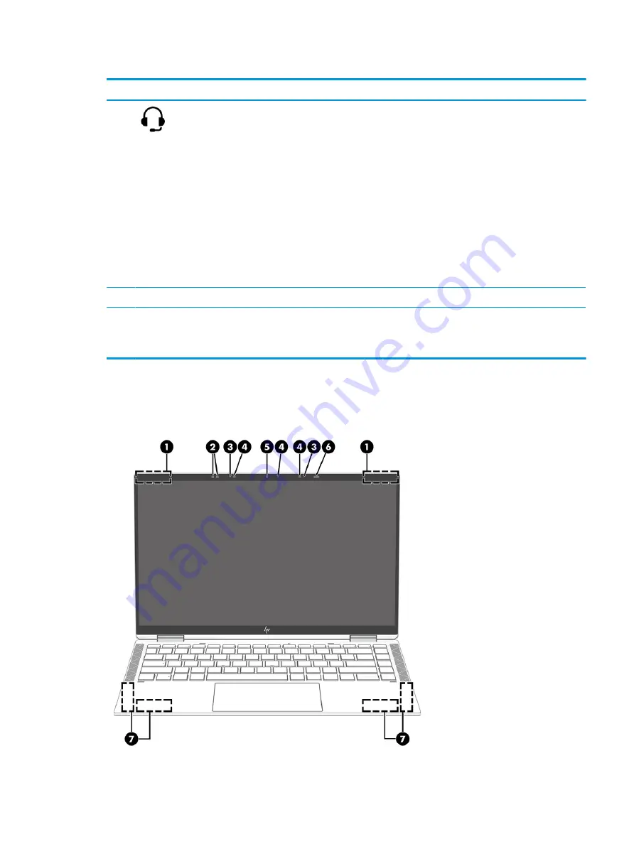
Display

Use the illustration and table to identify the display components.

ENWW

Display

7

Summary of Contents for EliteBook x360 1030

Page 1: ...Maintenance and Service Guide SUMMARY This guide provides information about spare parts removal and replacement of parts security backing up and more ...

Page 2: ...dition August 2020 Document Part Number M20567 001 Product notice This guide describes features that are common to most models Some features may not be available on your computer Not all features are available in all editions or versions of Windows Systems may require upgraded and or separately purchased hardware drivers software or BIOS update to take full advantage of Windows functionality Windo...

Page 3: ...the computer air vents Use the computer only on a hard flat surface Do not allow another hard surface such as an adjoining optional printer or a soft surface such as pillows or rugs or clothing to block airflow Also do not allow the AC adapter to come into contact with the skin or a soft surface such as pillows or rugs or clothing during operation The computer and the AC adapter comply with the us...

Page 4: ...iv Safety warning notice ENWW ...

Page 5: ...els 16 Inserting a nano SIM card select products only 18 3 Illustrated parts catalog 19 Computer major components 19 Mass storage devices 28 Cables 29 Miscellaneous parts 29 4 Removal and replacement procedures preliminary requirements 33 Tools required 33 Using HP PC Hardware Diagnostics 34 Downloading the HP PC Hardware Diagnostics Windows from the Microsoft Store 34 Customizing Remote HP PC Har...

Page 6: ...service provider parts 41 Component replacement procedures 42 Preparation for disassembly 42 Bottom cover 42 Battery 43 Solid state drive 45 WWAN module 46 Connector board cable 48 Connector board 49 Display assembly 50 Speakers 52 Touchpad cable 54 Touchpad 55 NFC module cable 57 NFC module 58 System board 58 Fan heat sink assembly 62 Sensor board cable 63 Sensor board 64 WWAN antenna 65 6 Using ...

Page 7: ...a 73 Changing the computer boot order 74 Using HP Sure Recover select products only 74 8 Specifications 75 Computer specifications 75 33 8 cm 13 3 in display specifications 76 Solid state drive specifications 76 Solid state drive specifications SATA 3 77 9 Statement of memory volatility 79 Current BIOS steps 79 Nonvolatile memory usage 81 Questions and answers 83 Using HP Sure Start select product...

Page 8: ...viii ENWW ...

Page 9: ...gh definition FHD 1920 1080 BrightView WLED 72 eDP PSR Sure View Reflect ultraslim touchscreen display panel typical brightness 1000 nits LCD 13 3 in FHD 1920 1080 BrightView WLED 72 eDP 1 4 PSR2 bent low power LP touchscreen display panel typical brightness 400 nits LCD 13 3 in FHD 1920 1080 antiglare WLED 72 eDP 1 4 PSR2 bent LP touchscreen display panel typical brightness 400 nits LCD 13 3 in F...

Page 10: ...lAryMic USB2 Dual array digital microphone Near field communications NFC NFC Mirage WNC XRAV 1 Wireless Wireless Local Area Network WLAN Intel Wi Fi 6 AX201 ax 2 2 Bluetooth 5 MU MIMO M 2 1216 vPro 160 MHz MIPI BRI WW with 2 antenna Intel Wi Fi 6 AX201 ax 2 2 Bluetooth 5 MU MIMO M 2 1216 non vPro 160 MHz MIPI BRI WW with 2 antenna Wireless Wide Area Network WWAN Intel XMM 7360 LTE Advanced Cat 9 Q...

Page 11: ...64 Plus Single Language Windows 10 Home 64 Plus Single Language Africa Market PPP Windows 10 Home 64 Plus Single Language APAC EM PPP Windows 10 Home 64 Plus Single Language India Market PPP Windows 10 Home 64 Plus Single Language Indonesia Market PPP Windows 10 Professional 64 Windows 10 Professional 64 CBB 1903 Windows 10 Professional 64 Chinese Market Windows 10 Professional 64 StF MSNA Plus Fr...

Page 12: ...4 Chapter 1 Product description ENWW ...

Page 13: ...en AC power is connected White The battery charge is greater than 90 percent Amber The battery charge is from 0 to 90 percent Off The battery is not charging When AC power is disconnected battery not charging Blinking amber The battery has reached a low battery level When the battery has reached a critical battery level the battery light begins blinking rapidly Off The battery is not charging ENWW...

Page 14: ...equired 3 HDMI port Connects an optional video or audio device such as a high definition television any compatible digital or audio component or a high speed High Definition Multimedia Interface HDMI device 4 USB SuperSpeed port with HP Sleep and Charge Connects a USB device provides high speed data transfer and charges small devices even when the computer is off Left Use the illustration and tabl...

Page 15: ... For additional safety information see the Regulatory Safety and Environmental Notices To access this guide Type HP Documentation in the taskbar search box and then select HP Documentation NOTE When a device is connected to the jack the computer speakers are disabled 3 Nano SIM card slot select products only Supports a wireless subscriber identity module SIM card 4 Security cable slot Attaches an ...

Page 16: ...ial recognition to monitor your presence in front of the computer to save power and add security When you step away from the computer the sensor puts the computer into the Sleep state When you return to your computer the sensor recognizes you and wakes the computer without a key press or mouse movement 7 WWAN antennas select products only Send and receive wireless signals to communicate with wirel...

Page 17: ...Keyboard area ENWW Keyboard area 9 ...

Page 18: ...ab key repeatedly until the pointer rests on the Touchpad button Then press the spacebar to select the button Table 2 4 Touchpad components and their descriptions Component Description 1 Touchpad zone Reads finger gestures to move the pointer or activate items on the screen 2 Left touchpad button Functions like the left button on an external mouse 3 Near Field Communications NFC tapping area and a...

Page 19: ... sound is on 4 Microphone mute light On Microphone is off Off Microphone is on 5 Camera privacy light On The camera is off Off The camera is on 6 Power light On The computer is on Blinking select products only The computer is in the Sleep state a power saving state The computer shuts off power to the display and other unnecessary components Off Depending on your computer model the computer is off ...

Page 20: ...pports fingerprint reader sign in type Sign in options in the taskbar search box and follow the on screen instructions If Fingerprint reader is not listed as an option then your notebook does not include a fingerprint reader Table 2 6 Button speaker and fingerprint reader components and their descriptions Component Description 1 Speakers 2 Produce sound 12 Chapter 2 Components ENWW ...

Page 21: ...e loss of unsaved information If the computer has stopped responding and shutdown procedures are ineffective press and hold the power button for at least 4 seconds to turn off the computer To learn more about your power settings see your power options Right click the Power meter icon and then select Power Options 3 Fingerprint reader Allows a fingerprint logon to Windows instead of a password logo...

Page 22: ...a off shutter closed and on If you record video when the camera is off shutter closed audio will still record 7 Power button When the computer is off press the button briefly to turn on the computer When the computer is on press the button briefly to initiate Sleep When the computer is in the Sleep state press the button briefly to exit Sleep select products only When the computer is in Hibernatio...

Page 23: ... and table to identify the bottom components Table 2 9 Bottom components and their descriptions Component Description 1 Speakers Produce sound 2 Vent Enables airflow to cool internal components NOTE The computer fan starts up automatically to cool internal components and prevent overheating It is normal for the internal fan to cycle on and off during routine operation Top cover Use the illustratio...

Page 24: ...TE The computer fan starts up automatically to cool internal components and prevent overheating It is normal for the internal fan to cycle on and off during routine operation Labels Use the illustration and table to identify the label location and components The labels affixed to the computer provide information you might need when you troubleshoot system problems or travel internationally with th...

Page 25: ...l number the product number or the model number Locate this information before you contact support Your service label will resemble one of the examples shown below Refer to the illustration that most closely matches the service label on your computer Table 2 12 Service label components and their descriptions Component 1 HP product name 2 Warranty period 3 Product ID 4 Serial number Table 2 13 Serv...

Page 26: ... components and their descriptions Component 1 HP product name 2 Product ID 3 Serial number 4 Warranty period Inserting a nano SIM card select products only To insert a SIM card follow these steps 18 Chapter 2 Components ENWW ...

Page 27: ...HP continually improves and changes product parts For complete and current information about supported parts for your computer go to http partsurfer hp com select your country or region and then follow the on screen instructions NOTE Details about your computer including model serial number product key and length of warranty are on the service tag on the bottom of your computer ENWW Computer major...

Page 28: ...cal brightness 400 nits M16087 001 LCD FHD 1920 1080 BrightView LED UWVA SVR touchscreen display assembly typical brightness 1000 nits M16089 001 LCD FHD 1920 1080 BrightView LED UWVA low power LP touchscreen display assembly typical brightness 400 nits M16086 001 LCD FHD 1920 1080 antiglare LED UWVA SVR touchscreen display assembly typical brightness 1000 nits M16088 001 20 Chapter 3 Illustrated ...

Page 29: ...e in Denmark M16982 081 For use in Denmark and Finland M16982 DH1 For use in France M16982 051 For use in Germany M16982 041 For use in Greece M16982 151 For use in Hungary M16982 211 For use in Iceland M16982 DD1 For use in India M16982 D61 For use in Israel M16982 BB1 For use in Italy M16982 061 For use in Japan M16982 291 For use in Latin America M16982 161 For use in the Netherlands M16982 B31...

Page 30: ...e in Bulgaria M16980 261 For use in Canada M16980 DB1 For use in the Czech Republic and Slovakia M16980 FL1 For use in Denmark M16980 081 For use in Denmark and Finland M16980 DH1 For use in France M16980 051 For use in Germany M16980 041 For use in Greece M16980 151 For use in Hungary M16980 211 For use in Iceland M16980 DD1 For use in India M16980 D61 For use in Israel M16980 BB1 For use in Ital...

Page 31: ...WAN capability includes backlight cable and keyboard cable For use in Belgium M16981 A41 For use in Brazil M16981 201 For use in Bulgaria M16981 261 For use in Canada M16981 DB1 For use in the Czech Republic and Slovakia M16981 FL1 For use in Denmark M16981 081 For use in Denmark and Finland M16981 DH1 For use in France M16981 051 For use in Germany M16981 041 For use in Greece M16981 151 For use ...

Page 32: ...e in the United States M16981 001 Top cover keyboard equipped with backlight for use only on computer models not equipped with WWAN capability includes backlight cable and keyboard cable For use in Belgium M16979 A41 For use in Brazil M16979 201 For use in Bulgaria M16979 261 For use in Canada M16979 DB1 For use in the Czech Republic and Slovakia M16979 FL1 For use in Denmark M16979 081 For use in...

Page 33: ...Touchpad NOTE The touchpad spare part kit does not include the touchpad bracket or touchpad cable The touchpad bracket is not available as a spare part The touchpad cable is available in the Cable Kit spare part number M20833 001 For use only on computer models equipped with NFC capability M16048 001 For use only on computer models not equipped with NFC capability M16056 001 4b Touchpad bracket Th...

Page 34: ...e Kit spare part number M20833 001 Nano SIM tray not illustrated for use only on computer models equipped with WWAN capability M16053 001 9 Fan heat sink assembly includes replacement thermal material and fan cables M16051 001 10 System board includes integrated processor and fan heat sink assembly Equipped with an Intel Core i7 10810U processor 32 GB of system memory and the Windows 10 OSR operat...

Page 35: ...tem memory and a non Windows OSR operating system M16065 001 Equipped with an Intel Core i7 10610U processor 16 GB of system memory and the Windows 10 OSR operating system M16064 601 Equipped with an Intel Core i7 10610U processor 16 GB of system memory and a non Windows OSR operating system M16064 001 Equipped with an Intel Core i7 10610U processor 8 GB of system memory and the Windows 10 OSR ope...

Page 36: ...t speakers cables and rubber isolators M16052 001 14 Bottom cover For use only on computer models equipped with WWAN capability M16044 001 For use only on computer models equipped not with WWAN capability M16043 001 Mass storage devices To identify the mass storage devices use this illustration and table Table 3 2 Mass storage device descriptions and part numbers Item Component Spare part number S...

Page 37: ... board cable Miscellaneous parts To identify the miscellaneous parts use this table Table 3 4 Miscellaneous part descriptions and part numbers Component Spare part number AC adapter 90 W AC adapter PFC S 3P 4 5 mm 710413 001 65 W AC adapter non PFC slim USB Type C straight 1 8 m L04650 850 65 W AC adapter non PFC USB Type C RC 1 8 m L32392 001 65 W AC adapter non PFC USB Type C 1 8 m L67440 001 HP...

Page 38: ...5809 001 Duckhead adapter C5NS premium sticker black for use in North America L50818 002 C5NS premium sticker black for use in South Korea L50818 001 Headset HP stereo 3 5 mm headset 840339 001 HP USB stereo headset 840340 001 HP nano lock 918431 001 Mouse HP Bluetooth travel mouse L62043 001 HP comfort grip wireless mouse 691922 001 HP USB travel mouse 757770 001 HP AES 2 0 pen with app button L5...

Page 39: ... 001 For use in India L22624 001 For use in Israel L22323 001 For use in Italy L30813 001 For use in Japan L22330 001 For use in North America L22319 001 For use in The People s Republic of China L21930 001 For use in South Africa L22325 001 For use in South Korea L22328 001 For use in Switzerland L22324 001 For use in Taiwan L22329 001 For use in Thailand L22326 001 For use in The United Kingdom ...

Page 40: ...ntional with sticker 1 0 m For use in Argentina L19357 001 For use in Australia L19358 001 For use in Brazil L19359 001 For use in Denmark L19360 001 For use in Europe L19361 001 For use in India L19363 001 For use in Israel L19362 001 For use in Italy L19364 001 For use in North America L19367 001 For use in The People s Republic of China L19368 001 For use in South Africa L19369 001 For use in S...

Page 41: ...ion to properly prepare to disassemble and reassemble the computer Tools required You need the following tools to complete the removal and replacement procedures Magnetic Phillips P1 screwdriver Nonconductive nonmarking pry tool Torx T6 screwdriver Tweezers ENWW Tools required 33 ...

Page 42: ...form several customizations Set a schedule for running diagnostics unattended You can also start diagnostics immediately in interactive mode by selecting Execute Remote HP PC Hardware Diagnostics Set the location for downloading the diagnostic tools This feature provides access to the tools from the HP website or from a server that has been preconfigured for use Your computer does not require the ...

Page 43: ...ing drives IMPORTANT Drives are fragile components Handle them with care To prevent damage to the computer damage to a drive or loss of information observe these precautions Before removing or inserting a hard drive shut down the computer If you are unsure whether the computer is off or in Hibernation turn the computer on and then shut it down through the operating system Before handling a drive b...

Page 44: ...es use fixtures made only of static safe materials Keep the work area free of nonconductive materials such as ordinary plastic assembly aids and polystyrene foam Handle ESD sensitive components parts and assemblies by the case or PCM laminate Handle these items only at static free workstations Avoid contact with pins leads or circuitry Turn off power and input signals before inserting or removing ...

Page 45: ...described Personal grounding methods and equipment on page 38 Avoid touching pins leads and circuitry Handle electronic components as little as possible If you remove a component place it in an electrostatic safe container Generating static electricity Follow these static electricity guidelines Different activities generate different amounts of static electricity Static electricity increases as hu...

Page 46: ...p must be worn snug against bare skin The ground cord must be connected and fit snugly into the banana plug connector on the grounding mat or workstation Heel straps Toe straps Boot straps can be used at standing workstations and are compatible with most types of shoes or boots On conductive floors or dissipative floor mats use them on both feet with a maximum of 1 MΩ 10 resistance between the ope...

Page 47: ...rist straps and footwear straps providing 1 MΩ 10 resistance Material handling packages Conductive plastic bags Conductive plastic tubes Conductive tote boxes Opaque shielding bags Transparent metallized shielding bags Transparent shielding tubes Packaging and transporting guidelines Follow these grounding guidelines when packaging and transporting equipment To avoid hand contact transport product...

Page 48: ...of antistatic belts and roller bushings Be sure that mechanized equipment used for moving materials is wired to ground and that proper materials are selected to avoid static charging When grounding is not possible use an ionizer to dissipate electric charges 40 Chapter 4 Removal and replacement procedures preliminary requirements ENWW ...

Page 49: ...vice provider parts IMPORTANT Components described in this chapter should be accessed only by an authorized service provider Accessing these parts can damage the computer or void the warranty NOTE Details about your computer including model serial number product key and length of warranty are on the service tag at the bottom of your computer ENWW 41 ...

Page 50: ... 1 Turn off the computer If you are unsure whether the computer is off or in Hibernation turn the computer on and then shut it down through the operating system 2 Disconnect the power from the computer by unplugging the power cord from the computer 3 Disconnect all external devices from the computer Bottom cover To remove the bottom cover use this procedure and illustration Table 5 1 Bottom cover ...

Page 51: ...cover from the computer 3 To replace the bottom cover reverse the removal procedures Battery To remove the battery use this procedure and illustration Table 5 2 Battery description and part number Description Spare part number Battery 4 cell 78 Whr 5 09 Ahr LI includes cable L82391 006 ENWW Component replacement procedures 43 ...

Page 52: ...ollow these steps 1 Prepare the computer for disassembly Preparation for disassembly on page 42 2 Remove the bottom cover Bottom cover on page 42 WARNING To reduce potential safety issues use only the user replaceable battery provided with the computer a replacement battery provided by HP or a compatible battery purchased from HP IMPORTANT Removing a battery that is the sole power source for the c...

Page 53: ...5 256 GB M 2 2280 PCIe NVMe SED solid state drive with TLC M07245 005 256 GB M 2 2280 PCIe NVMe value solid state drive L85354 005 128 GB M 2 2280 SATA 3 solid state drive with TLC L85346 005 512 GB M 2 2280 PCIe 32 GB 3D Xpoint solid state drive L85366 005 256 GB M 2 2280 PCIe 16 GB 3D Xpoint solid state drive L85356 005 Before removing the solid state drive follow these steps 1 Prepare the compu...

Page 54: ...socket to remove it To install the solid state drive reverse the removal procedures NOTE Solid state drives are designed with a notch to prevent incorrect insertion WWAN module To remove the WWAN module use this procedure and illustration 46 Chapter 5 Removal and replacement procedures for authorized service provider parts ENWW ...

Page 55: ...and then contact technical support Before removing the WWAN module follow these steps 1 Prepare the computer for disassembly Preparation for disassembly on page 42 2 Remove the bottom cover Bottom cover on page 42 3 Disconnect the battery cable from the system board Battery on page 43 Remove the WWAN module 1 Disconnect the WWAN antenna cables 1 from the terminals on the WWAN module NOTE The 5 blu...

Page 56: ...AN module a protective sleeve must be installed on the antenna connector as shown in the following illustration Reverse this procedure to install the WWAN module Connector board cable To remove the connector board cable use this procedure and illustration 48 Chapter 5 Removal and replacement procedures for authorized service provider parts ENWW ...

Page 57: ...h the connector board cable is connected and then disconnect the cable from the connector board 3 Remove the connector board cable 3 Reverse this procedure to install the connector board cable Connector board To remove the connector board use this procedure and illustration Table 5 5 Connector board description and part number Description Spare part number Connector board includes audio out headph...

Page 58: ...sconnect the cable from the system board 3 Remove the two Phillips M2 0 5 0 screws 3 that secure the connector board to the computer 4 Remove the connector board 4 and cable Reverse this procedure to install the connector board Display assembly To remove and disassemble the display assembly use these procedures and illustrations Before removing the display panel follow these steps 1 Prepare the co...

Page 59: ... which the webcam microphone module cable is connected and disconnect the cable from the system board 4 Release the WLAN antenna cables and the webcam microphone module cable from the retention clip 4 built into the top cover keyboard 5 Release the ZIF connector 5 to which the display panel cable is connected and disconnect the cable from the system board 6 Release the display panel cable from the...

Page 60: ...eyboard The top cover keyboard disengages from the display assembly hinges 9 Separate the display assembly 2 from the top cover keyboard Reverse this procedure to reassemble and replace the display assembly Speakers To remove the speakers use this procedure and illustration 52 Chapter 5 Removal and replacement procedures for authorized service provider parts ENWW ...

Page 61: ...onnect the right speaker cable 1 from the system board 3 Release the WWAN antenna cable from the retention channel 2 built into the right speaker 4 Remove the three Phillips M2 0 3 5 screws 3 that secure the right speaker to the computer 5 Remove the right speaker 4 NOTE When removing the right speaker make note of the location of the rubber isolators 5 The absence of or damage to these isolators ...

Page 62: ...t number M20833 001 Before removing the touchpad cable follow these steps 1 Prepare the computer for disassembly Preparation for disassembly on page 42 2 Remove the bottom cover Bottom cover on page 42 3 Remove the battery Battery on page 43 Remove the touchpad cable 1 Release the ZIF connector 1 to which the touchpad cable is connected and then disconnect the cable from the system board 2 Release...

Page 63: ...ion for disassembly on page 42 2 Remove the bottom cover Bottom cover on page 42 3 Remove the battery Battery on page 43 Remove the touchpad 1 Detach the touchpad cable 1 from the top cover keyboard The touchpad cable is attached to the top cover keyboard with double sided adhesive 2 Release the ZIF connector 2 to which the touchpad cable is connected and then disconnect the cable from the system ...

Page 64: ...sible 6 Remove the three Phillips M2 0 2 0 broad head screws 1 that secure the touchpad to the computer 7 Remove the touchpad bracket 2 8 Lift the front edge 3 of the touchpad until it clears the top cover keyboard 9 Remove the touchpad from the computer 4 Reverse this procedure to install the touchpad 56 Chapter 5 Removal and replacement procedures for authorized service provider parts ENWW ...

Page 65: ...he computer for disassembly Preparation for disassembly on page 42 2 Remove the bottom cover Bottom cover on page 42 3 Remove the battery Battery on page 43 Remove the NFC module cable 1 Detach the NFC module cable 1 from the top cover keyboard The NFC module cable cable is attached to the top cover keyboard with double sided adhesive 2 Release the ZIF connector 2 to which the NFC module cable cab...

Page 66: ...over on page 42 3 Remove the battery Battery on page 43 Remove the NFC module 1 Detach the NFC module cable cable 1 from the top cover keyboard The NFC module cable cable is attached to the top cover keyboard with double sided adhesive 2 Release the ZIF connector 2 to which the NFC module cable cable is connected and then disconnect the cable from the system board 3 Detach the NFC module 3 from th...

Page 67: ...d with an OLED display assembly M16068 001 Equipped with an Intel Core i7 10710U processor 16 GB of system memory and the Windows 10 operating system for use only with computer models not equipped with an OLED display assembly M16066 601 Equipped with an Intel Core i7 10710U processor 16 GB of system memory and a non Windows operating system for use only with computer models not equipped with an O...

Page 68: ...quipped with an Intel Core i5 10310U processor 8 GB of system memory and a non Windows operating system M16057 001 Before removing the system board follow these steps 1 Prepare the computer for disassembly Preparation for disassembly on page 42 2 Remove the bottom cover Bottom cover on page 42 3 Remove the battery Battery on page 43 4 Remove the WWAN module see WWAN module on page 46 When you repl...

Page 69: ...able 7 Fingerprint cable ZIF connector cable 8 NFC module cable ZIF connector cable 9 Left speaker cable 10 5 Remove the four Phillips M2 0 5 0 screws that secure the system board to the computer 6 Lift the front edge of the system board 1 until it rests at an angle ENWW Component replacement procedures 61 ...

Page 70: ...se steps 1 Prepare the computer for disassembly Preparation for disassembly on page 42 2 Remove the bottom cover Bottom cover on page 42 3 Remove the battery Battery on page 43 4 Remove the system board System board on page 58 Remove the fan heat sink assembly 1 Disconnect the fan cables 1 from the system board 2 In the order indicated on the fan heat sink assembly remove the four captive Phillips...

Page 71: ...are part kits The following illustration shows the replacement thermal material locations Thermal paste is used on the processor 1 and on the fan heat sink assembly area 2 that services it Reverse this procedure to install the fan heat sink assembly Sensor board cable To remove the sensor board cable use this procedure and illustration NOTE The sensor board cable is available in the Cable Kit spar...

Page 72: ...cted and then disconnect the cable from the sensor board 4 Remove the sensor board cable 3 Reverse this procedure to install the sensor board cable Sensor board To remove the sensor board use this procedure and illustration Table 5 12 Sensor board description and part number Description Spare part number Sensor board NOTE The sensor board spare part kit does not include the sensor board cable The ...

Page 73: ...ble is connected and then disconnect the cable from the system board 3 Detach the sensor board 2 from the system board The sensor board is attached to the system board with double sided adhesive 4 Remove the sensor board 3 and cable Reverse this procedure to install the sensor board WWAN antenna To remove the WWAN antenna use this procedure and illustration Table 5 13 WWAN antenna description and ...

Page 74: ...transceivers 1 from the top cover keyboard surface The transceivers are attached to the top cover keyboard with double sided adhesive 2 Release the cables 2 from the routing path to which they are formed in the top cover keyboard 3 Release the cables from the rubber retention molds 3 4 Remove the WWAN antenna Reverse this procedure to install the WWAN antenna 66 Chapter 5 Removal and replacement p...

Page 75: ... and extended memory NOTE To start Setup Utility on convertible computers your computer must be in notebook mode and you must use the keyboard attached to your notebook Starting Setup Utility BIOS You have several ways to access the Setup Utility BIOS IMPORTANT Use extreme care when making changes in Setup Utility BIOS Errors can prevent the computer from operating properly Turn on or restart the ...

Page 76: ...e BIOS version information also known as ROM date and System BIOS use one of these options HP Support Assistant 1 Type support in the taskbar search box and then select the HP Support Assistant app or Select the question mark icon in the taskbar 2 Select My notebook and then select Specifications Setup Utility BIOS 1 Start Setup Utility BIOS see Starting Setup Utility BIOS on page 67 2 Select Main...

Page 77: ...elect the HP Support Assistant app or Select the question mark icon in the taskbar 2 Select Updates and then select Check for updates and messages 3 Follow the on screen instructions 4 At the download area follow these steps a Identify the most recent BIOS update and compare it to the BIOS version currently installed on your computer If the update is more recent than your BIOS version make a note ...

Page 78: ...e exe The BIOS installation begins 5 Complete the installation by following the on screen instructions NOTE After a message on the screen reports a successful installation you can delete the downloaded file from your hard drive 70 Chapter 6 Using Setup Utility BIOS ENWW ...

Page 79: ... to its factory state Performing these standard procedures can return your computer to a working state faster IMPORTANT If you will be performing recovery procedures on a tablet the tablet battery must be at least 70 charged before you start the recovery process IMPORTANT For a tablet with a detachable keyboard connect the tablet to the keyboard base before beginning any recovery process ENWW 71 ...

Page 80: ...se the HP Cloud Recovery Download Tool to create HP Recovery media on a bootable USB flash drive For details Go to http www hp com support search for HP Cloud Recovery and then select the result that matches the type of computer that you have NOTE If you cannot create recovery media yourself contact support to obtain recovery discs Go to http www hp com support select your country or region and th...

Page 81: ...t the Start button select the Get Help app and then enter the task you want to perform NOTE You must be connected to the internet to access the Get Help app Recovering using HP Recovery media You can use HP Recovery media to recover the original operating system and software programs that were installed at the factory On select products it can be created on a bootable USB flash drive using the HP ...

Page 82: ...the volume up button and then select f9 or Turn on or restart the tablet quickly press and hold the volume down button and then select f9 3 Select the optical drive or USB flash drive from which you want to boot and then follow the on screen instructions Using HP Sure Recover select products only Select computer models are configured with HP Sure Recover a PC OS recovery solution built into the ha...

Page 83: ... Metric U S Dimensions Width 385 mm 15 18 in Depth 258 mm 10 15 in Height front to back 23 mm 0 89 in Weight 2 09 kg 4 61 lb Input power Operating voltage and current 19 5 V dc 2 31 A 45 W 19 5 V dc 3 33 A 65 W 19 5 V dc 4 62 A 90 W 19 5 V dc 7 70 A 150 W 19 5 V dc 10 3 A 200 W Temperature Operating 5 C to 35 C 41 F to 95 F Nonoperating 20 C to 60 C 4 F to 140 F Relative humidity noncondensing Ope...

Page 84: ...3840 2160 UHD Surface treatment Antiglare FHD UHD panels BrightView OLED panel Brightness 400 nits UHD sRGB 95 panel 1000 nits FHD 72 NTSC panels 400 nits FHD 72 NTSC panels Viewing angle UWVA Backlight WLED Display panel interface eDP 1 4 PSR2 eDP PSR Solid state drive specifications This section provides specifications for your solid state drives Table 8 3 Solid state drive specifications 256 GB...

Page 85: ...ity is less Actual drive specifications can differ slightly NOTE Certain restrictions and exclusions apply Contact support for details Solid state drive specifications SATA 3 This section provides specifications for your solid state drive Table 8 4 Solid state drive specifications 128 GB Dimensions Height 1 35 mm Weight 10 g Interface type SATA 3 Ready time maximum to not busy 1 0 ms Access times ...

Page 86: ...78 Chapter 8 Specifications ENWW ...

Page 87: ...y Use the following steps to remove personal data from the computer including the nonvolatile memory found in Intel based and AMD based system boards NOTE If your tablet has a keyboard base connect to the keyboard base before beginning steps in this chapter Current BIOS steps Use these instructions to restore nonvolatile memory 1 Follow these steps to restore the nonvolatile memory that can contai...

Page 88: ...er the password at the prompt j Select the Main menu select Apply Factory Defaults and Exit select Yes to save changes and exit and then select Shutdown k Reboot the system If the system has a Trusted Platform Module TPM fingerprint reader or both one or two prompts will appear one to clear the TPM and the other to Reset Fingerprint Sensor Press or tap f1 to accept or f2 to reject l Remove all pow...

Page 89: ...protected backup of critical System BIOS code EC firmware and critical computer configuration data for select platforms that support HP Sure Start For more information see Using HP Sure Start select products only on page 85 Data cannot be written to this device via the host processor The content is managed solely by the HP Sure Start Embedded Controller This memory is protected by the HP Sure Star...

Page 90: ...e on screen instructions 1 5 MB or 7 MB Yes Yes Stores Management Engine Code Settings Provisioning Data and iAMT third party data store Management Engine Code is programmed at the factory Code is updated via Intel secure firmware update utility Unique Provisioning Data can be entered at the factory or by an administrator using the Management Engine MEBx setup utility The third party data store co...

Page 91: ...e Fingerprint reader select products only 512 KB flash Yes Yes Stores fingerprint templates Fingerprint reader memory is programmed by user enrollment in HP ProtectTools Security Manager Only a digitally signed application can make the call to write to the flash Questions and answers Use this section to answer your questions about nonvolatile memory 1 How can the BIOS settings be restored returned...

Page 92: ...ent and recovery software HP has provided options in Computer Setup BIOS to allow you to run in legacy BIOS if required by the operating system Examples of this requirement would be if you upgrade or downgrade the OS 3 Where is the UEFI BIOS located The UEFI BIOS is located on a flash memory chip You must use a utility to write to the chip 4 What kind of configuration data is stored on the DIMM Se...

Page 93: ...tion and then follow the on screen instructions c At the Secure Boot Configuration window select Secure Boot select Clear Secure Boot Keys and then follow the on screen instructions to continue Using HP Sure Start select products only Select computer models are configured with HP Sure Start a technology that continuously monitors your computer s BIOS for attacks or corruption If the BIOS becomes c...

Page 94: ...86 Chapter 9 Statement of memory volatility ENWW ...

Page 95: ... no more than 2 0 m 6 5 ft All power cord sets must be approved by an acceptable accredited agency responsible for evaluation in the country or region where the power cord set will be used The power cord sets must have a minimum current capacity of 10 A and a nominal voltage rating of 125 V ac or 250 V ac as required by the power system of each country or region The appliance coupler must meet the...

Page 96: ... France UTE 1 Germany VDE 1 India BIS 1 Israel SII 1 Italy IMQ 1 Japan JIS 3 The Netherlands KEMA 1 New Zealand SANZ 1 Norway NEMKO 1 The People s Republic of China CCC 4 Saudi Arabia SASO 7 Singapore PSB 1 South Africa SABS 1 South Korea KTL 5 Sweden SEMKO 1 Switzerland SEV 1 Taiwan BSMI 6 Thailand TISI 1 The United Kingdom ASTA 1 88 Chapter 10 Power cord set requirements ENWW ...

Page 97: ...CTF 3 conductor 0 75 mm or 1 25 mm conductor size The wall plug must be a two pole grounding type with a Japanese Industrial Standard C8303 7 A 125 V ac configuration 4 The flexible cord must be Type RVV 3 conductor 0 75 mm conductor size Power cord set fittings appliance coupler and wall plug must bear the CCC certification mark 5 The flexible cord must be Type H05VV F 3 conductor 0 75 mm conduct...

Page 98: ...90 Chapter 10 Power cord set requirements ENWW ...

Page 99: ...battery in general household waste Follow the local laws and regulations in your area for battery disposal HP encourages customers to recycle used electronic hardware HP original print cartridges and rechargeable batteries For more information about recycling programs see the HP website at http www hp com recycle ENWW 91 ...

Page 100: ...92 Chapter 11 Recycling ENWW ...

Page 101: ...major components 19 computer specifications 75 connector board removal 49 spare part number 49 connector board cable illustrated 29 removal 48 spare part number 29 48 D display specifications 75 76 display components 7 E electrostatic discharge ESD 33 37 preventing damage 33 37 38 esc key 14 F fan heat sink assembly removal 62 spare part number 62 fingerprint reader 13 14 fingerprint reader compon...

Page 102: ...g 71 right side components 5 S Screw Kit spare part number 29 sensor board removal 64 spare part numbers 64 sensor board cable illustrated 29 removal 63 spare part number 29 63 settings touchpad 10 SIM card inserting 18 solid state drive removal and replacement 45 spare part numbers 28 specifications 76 77 speaker removal 52 spare part numbers 52 speakers components 12 location 12 15 special key c...

Reviews: