


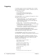
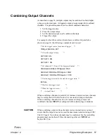


Combining Output Channels
As described on page 34, multiple outputs may be combined to obtain higher
voltage or current outputs. A triggered output is recommended for combined
channels. The general sequence used to control combined channels is:
1. Set the trigger source.
2. Close the output relays.
3. Set the desired output on all combined channels.
4. Trigger the output.
For example, when three current channels are combined in parallel as
shown on page 34, the following commands can be used.
/* Set the trigger source for external trigger */
TRIGger:SOURce EXT
/* Close the output relays */
OUTPut9 ON
OUTPut10 ON
OUTPut11 ON
/* Set channels 9, 10, and 11 for triggered output */
SOURce9:CURRent:TRIGgered MAX
SOURce10:CURRent:TRIGgered MAX
SOURce11:CURRent:TRIGgered .0100
/* Put the trigger system in the wait-for-trigger state */
INITiate
/* Wait for the trigger event */
/* When the trigger occurs
…
*/
/*
…
output 50 mA */
When combining channels in parallel, for increased current output, channels
may be configured with either isolated or non-isolated plug-on modules.
When combining channels in series, for increased voltage output, all
combined channels MUST be configured with isolated plug-on modules.
CAUTION
When combining output voltage channels (series connections) you must
ensure that the output does not exceed the maximum isolation rating of
±
42
Vdc/42 Vpeak. Up to three channels may be combined, but the controlling
program must ensure that all three channels together are NEVER set
beyond
±
42 Vdc.
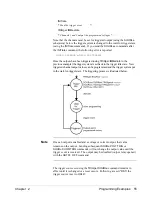
Notes
Chapter 2
Programming Examples 57
Summary of Contents for E1418A
Page 6: ...Notes 6 Contents HP E1418A 8 16 Channel D A Converter Module ...
Page 10: ...Notes 10 HP E1418A User s Manual ...
Page 12: ...12 HP E1418A User s Manual ...
Page 105: ...TRIGger 105 HP E1418A SCPI Command Reference Chapter 3 ...
Page 111: ...Notes HP E1418A Command Quick Reference 111 HP E1418A SCPI Command Reference Chapter 3 ...
Page 135: ...135 HP E1418A Register Based Programming Appendix B ...
Page 157: ...Notes 156 HP E1418A Error Messages Appendix C ...
Page 170: ...Notes Appendix D Voltage Current Output Adjustment 169 ...
Page 174: ...Figure E 1 8 Channel Disassembly 172 Configuration and Disassembly Appendix E ...
Page 175: ...Figure E 2 16 Channel Disassembly Appendix E Configuration and Disassembly 173 ...
Page 192: ...Notes 192 HP E1418A 8 16 Channel D A Converter Module Index ...


