background image

Connector board

Table 5-5

  Connector board spare part information

Description

Spare part number

Connector board (includes HDMI jack and USB port)

L90437-001

Before removing the connector board, follow these steps:

1.

Shut down the computer. If you are unsure whether the computer is off or in Hibernation, turn 
the computer on, and then shut it down through the operating system.

2.

Disconnect all external devices connected to the computer.

3.

Disconnect the power from the computer by first unplugging the power cord from the AC outlet, and then 
unplugging the AC adapter from the computer.

4.

Remove the keyboard/top cover (see 

Keyboard/top cover on page 20

).

5.

Disconnect the battery cable from the system board (see 

Battery on page 26

).

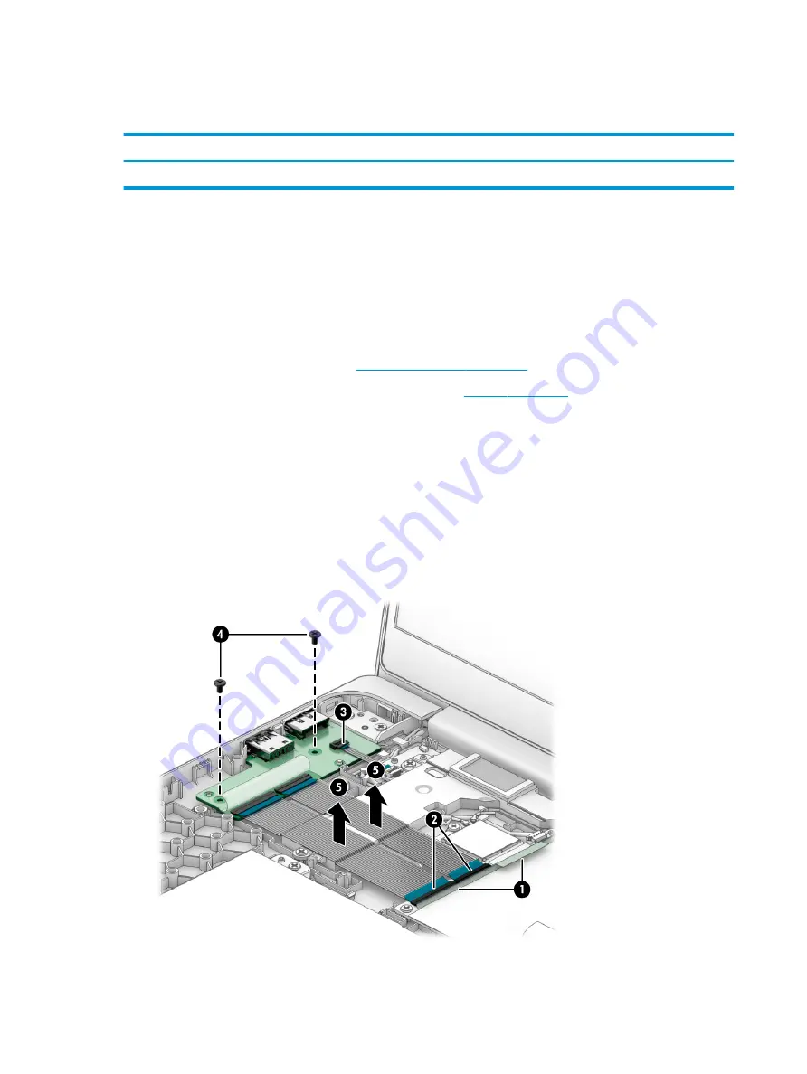
Remove the connector board:

1.

Release the shielding (1) that covers the connector board cable ZIF connectors.

2.

Release the ZIF connectors (2) to which the connector board cables are connected, and then disconnect 
the connector board cables from the system board.

3.

Release the ZIF connector (3) to which the sensor board cable is connected, and then disconnect the sensor 
board cable from the connector board.

4.

Remove the two Phillips M2.0×4.2 screws (4) that secure the connector board to the bottom cover.

5.

Remove the connector board (5) and cables.

Reverse this procedure to install the connector board.

30

Chapter 5   Removal and replacement procedures

Summary of Contents for Chromebook 14 G6

Page 1: ...Maintenance and Service Guide HP Chromebook 14 G6 IMPORTANT This document is intended for HP authorized service providers only ...

Page 2: ...t be liable for technical or editorial errors or omissions contained herein First Edition January 2020 Document Part Number L89294 001 Product notice This guide describes features that are common to most models Some features may not be available on the computer To access the latest user guides go to http www hp com support and follow the instructions to find your product Then select User Guides So...

Page 3: ...e device only on a hard flat surface Do not allow another hard surface such as an adjoining optional printer or a soft surface such as pillows or rugs or clothing to block airflow Also do not allow the AC adapter to contact the skin or a soft surface such as pillows or rugs or clothing during operation The device and the AC adapter comply with the user accessible surface temperature limits iii ...

Page 4: ...iv Safety warning notice ...

Page 5: ...nary requirements 15 Tools required 15 Service considerations 15 Plastic parts 15 Cables and connectors 15 Drive handling 16 Electrostatic discharge damage 16 Packaging and transporting guidelines 17 Workstation guidelines 18 Equipment guidelines 18 5 Removal and replacement procedures 20 Component replacement procedures 20 Keyboard top cover 20 Touchpad cable 24 Touchpad 25 Battery 26 WLAN module...

Page 6: ... System board 34 Display assembly 37 6 Specifications 49 Computer specifications 49 7 Power cord set requirements 51 Requirements for all countries 51 Requirements for specific countries and regions 52 8 Recycling 54 Index 55 vi ...

Page 7: ...20 1080 antiglare WLED UWVA LCD eDP slim non touchscreen display with narrow bezel typical brightness 250 nits 14 0 in high definition HD 1366 768 brightview WLED SVA LCD slim touchscreen display with narrow bezel and privacy shutter typical brightness 220 nits 14 0 in HD 1366 768 brightview WLED SVA LCD slim touchscreen display with narrow bezel typical brightness 220 nits 14 0 in HD 1366 768 ant...

Page 8: ...module Keyboard pointing devices Backlit island style spill resistant standard notebook keyboard in chalkboard gray finish Touchpad Power requirements Supports a 2 cell 47 36 WHr 6 15 AHr Li ion battery Supports a 45 W AC adapter non PFC standard USB Type C straight connector Supports a 1 meter C5 power cord Operating system Preinstalled Chrome64 Serviceability End user replaceable parts AC adapte...

Page 9: ...TE When a device is connected to the jack the computer speakers are disabled 2 microSD memory card reader Reads optional memory cards that store manage share or access information To insert a card 1 Hold the card label side up with connectors facing the computer 2 Insert the card into the memory card reader and then press in on the card until it is firmly seated To remove a card Push the card to r...

Page 10: ...able is designed to act as a deterrent but it may not prevent the computer from being mishandled or stolen 2 HDMI port Connects a USB device with a Type C connector and can charge products such as cell phones cameras activity trackers or smart watches even when the computer is off Also connects an AC adapter that has a USB Type C connector supplying power to the computer and if needed charging the...

Page 11: ... and online chat by means of streaming video 4 Privacy shutter Covers the camera for privacy 5 Camera light On the camera is in use The antennas are not visible from the outside of the computer and antenna location varies For optimal transmission keep the areas immediately around the antennas free from obstructions For wireless regulatory notices see the section of the Regulatory Safety and Enviro...

Page 12: ...Touchpad Component Description Touchpad zone Reads your finger gestures to move the pointer or activate items on the screen 6 Chapter 2 Components ...

Page 13: ...on will be affixed to the bottom of the computer Service label Provides important information to identify your computer When contacting support you will probably be asked for the serial number and possibly for the product number or the model number Locate these numbers before you contact support Your service label will resemble one of the following examples Refer to the illustration that most clos...

Page 14: ...oduct ID 3 Serial number 4 Warranty period Regulatory label s Provide s regulatory information about the computer Wireless certification label s Provide s information about optional wireless devices and the approval markings for the countries or regions in which the devices have been approved for use 8 Chapter 2 Components ...

Page 15: ...and changes product parts For complete and current information about supported parts for your computer go to http partsurfer hp com select your country or region and then follow the on screen instructions Computer major components Computer major components 9 ...

Page 16: ... L90460 061 For use in Latin America L90460 161 For use in the Netherlands L90460 B31 For use in Portugal L90460 131 For use in Romania L90460 271 For use in Russia L90460 251 For use in Saudi Arabia L90460 171 For use in South Korea L90460 AD1 For use in Spain L90460 071 For use in Switzerland L90460 BG1 For use in Taiwan L90460 AB1 For use in Thailand L90460 281 For use in Turkey L90460 141 For ...

Page 17: ...USB port L90437 001 5b Connector board high speed cable included in the Cable Kit spare part number L90412 001 5c Connector board low speed cable included in the Cable Kit spare part number L90412 001 6 Speakers include left and right speakers and cables L90434 001 7a Sensor board L90433 001 7b Sensor board cable included in the Cable Kit spare part number L90412 001 8a System board includes proce...

Page 18: ...C system storage and the Google Chrome operating system L90423 001 Equipped with an Intel Celeron N4020 processor 4 GB of system memory 32 GB of eMMC system storage and the Google Chrome operating system L90421 001 Equipped with an Intel Celeron N4020 processor 4 GB of system memory 16 GB of eMMC system storage and the Google Chrome operating system L90420 001 8b I O bracket L90438 001 9 Battery 2...

Page 19: ...hscreen display panel L90428 001 14 0 in HD brightview LED SVA touchscreen display panel L90431 001 14 0 in HD antiglare LED SVA non touchscreen display panel L90430 001 6 Display panel cable For use only on computers equipped with a touchscreen display assembly L90419 001 For use only on computers equipped with a non touchscreen display assembly L90418 001 7 Webcam module cable included in the Ca...

Page 20: ...onventional with sticker For use in Australia L19358 001 For use in Brazil L19359 001 For use in Denmark L19360 001 For use in Europe L19361 001 For use in India L19363 001 For use in Israel L19362 001 For use in Italy L19364 001 For use in North America L19367 001 For use in South Africa L19369 001 For use in South Korea L19366 001 For use in Switzerland L19370 001 For use in Taiwan L19372 001 Fo...

Page 21: ...sing excessive force during disassembly and reassembly can damage plastic parts Use care when handling the plastic Cables and connectors IMPORTANT When servicing the computer be sure that cables are placed in their proper locations during the reassembly process Improper cable placement can damage the computer Cables must be handled with extreme care to avoid damage Apply only the tension required ...

Page 22: ...itive to electrostatic discharge ESD Circuitry design and structure determine the degree of sensitivity Networks built into many integrated circuits provide some protection but in many cases ESD contains enough power to alter device parameters or melt silicon junctions A discharge of static electricity from a finger or other conductor can destroy static sensitive devices or microcircuitry Even if ...

Page 23: ...ipment To avoid hand contact transport products in static safe tubes bags or boxes Protect ESD sensitive parts and assemblies with conductive or approved containers or packaging Keep ESD sensitive parts in their containers until the parts arrive at static free workstations Place items on a grounded surface before removing items from their containers Always be properly grounded when touching a comp...

Page 24: ...inimum of 1 MΩ 10 resistance in the ground cords To provide proper ground wear a strap snugly against the skin at all times On grounded mats with banana plug connectors use alligator clips to connect a wrist strap When standing use foot straps and a grounded floor mat Foot straps heel toe or boot straps can be used at standing workstations and are compatible with most types of shoes or boots On co...

Page 25: ...tic bags and floor mats Table 4 2 Shielding protection provided by antistatic bags and floor mats Material Use Voltage protection level Antistatic plastics Bags 1 500 V Carbon loaded plastic Floor mats 7 500 V Metallized laminate Floor mats 5 000 V Equipment guidelines 19 ...

Page 26: ...in South Korea L90460 AD1 For use in Belgium L90460 A41 For use in Italy L90460 061 For use in Spain L90460 071 For use in Brazil L90460 201 For use in Latin America L90460 161 For use in Switzerland L90460 BG1 For use in Canada L90460 DB1 For use in the Netherlands L90460 B31 For use in Taiwan L90460 AB1 For use in the Czech Republic and Slovakia L90460 FL1 For use in Portugal L90460 131 For use ...

Page 27: ...90459 031 For use in Germany L90459 041 For use in Saudi Arabia L90459 171 For use in the United States L90459 001 Remove the keyboard top cover 1 Shut down the computer If you are unsure whether the computer is off or in Hibernation turn the computer on and then shut it down through the operating system 2 Disconnect all external devices connected to the computer 3 Disconnect the power from the co...

Page 28: ... covers the touchpad cable zero insertion force ZIF connector the keyboard cable ZIF connector and the backlight cable ZIF connector 12 Release the ZIF connector 3 to which the touchpad cable is connected and then disconnect the touchpad cable from the system board 13 Release the ZIF connector 4 to which the keyboard cable is connected and then disconnect the keyboard cable from the system board 1...

Page 29: ...15 Remove the keyboard top cover 6 Reverse this procedure to install the keyboard top cover Component replacement procedures 23 ...

Page 30: ... unplugging the AC adapter from the computer 4 Remove the keyboard top cover see Keyboard top cover on page 20 Remove the touchpad cable 1 Turn the keyboard top cover upside down with the front toward you 2 Release the shielding 1 that covers the touchpad cable ZIF connector 3 Release the ZIF connector 2 to which the touchpad cable is connected and then disconnect the touchpad cable from the touch...

Page 31: ...et and then unplugging the AC adapter from the computer 4 Remove the keyboard top cover see Keyboard top cover on page 20 Remove the touchpad 1 Turn the keyboard top cover upside down with the front toward you 2 Remove the four Phillips M2 0 2 9 screws 1 that secure the touchpad and touchpad bracket to the keyboard top cover 3 Remove the touchpad bracket 2 The touchpad bracket is available using s...

Page 32: ...l external devices connected to the computer 3 Disconnect the power from the computer by first unplugging the power cord from the AC outlet and then unplugging the AC adapter from the computer 4 Remove the keyboard top cover see Keyboard top cover on page 20 Remove the battery 1 Release the support tape 1 that secures the battery cable to the system board 2 Disconnect the battery cable 2 from the ...

Page 33: ... is off or in Hibernation turn the computer on and then shut it down through the operating system 2 Disconnect all external devices connected to the computer 3 Disconnect the power from the computer by first unplugging the power cord from the AC outlet and then unplugging the AC adapter from the computer 4 Remove the keyboard top cover see Keyboard top cover on page 20 5 Disconnect the battery cab...

Page 34: ...dule 3 by pulling the module away from the slot at an angle NOTE WLAN modules are notched to prevent incorrect installation Reverse this procedure to install the WLAN module 28 Chapter 5 Removal and replacement procedures ...

Page 35: ... adapter from the computer 4 Remove the keyboard top cover see Keyboard top cover on page 20 5 Disconnect the battery cable from the system board see Battery on page 26 Remove the connector board cables 1 Release the shielding 1 that covers the connector board cable ZIF connectors 2 Release the ZIF connectors 2 to which the connector board cables are connected and then disconnect the connector boa...

Page 36: ...4 Remove the keyboard top cover see Keyboard top cover on page 20 5 Disconnect the battery cable from the system board see Battery on page 26 Remove the connector board 1 Release the shielding 1 that covers the connector board cable ZIF connectors 2 Release the ZIF connectors 2 to which the connector board cables are connected and then disconnect the connector board cables from the system board 3 ...

Page 37: ... cord from the AC outlet and then unplugging the AC adapter from the computer 4 Remove the keyboard top cover see Keyboard top cover on page 20 5 Disconnect the battery cable from the system board see Battery on page 26 Remove the sensor board cable 1 Release the ZIF connector 1 to which the sensor board cable is connected and then disconnect the sensor board cable from the system board 2 Release ...

Page 38: ... the computer by first unplugging the power cord from the AC outlet and then unplugging the AC adapter from the computer 4 Remove the keyboard top cover see Keyboard top cover on page 20 5 Disconnect the battery cable from the system board see Battery on page 26 Remove the speakers 1 Release the shielding 1 that secures the speaker cable to the system board and covers the speaker cable connector 2...

Page 39: ...r 3 Disconnect the power from the computer by first unplugging the power cord from the AC outlet and then unplugging the AC adapter from the computer 4 Remove the keyboard top cover see Keyboard top cover on page 20 5 Disconnect the battery cable from the system board see Battery on page 26 6 Remove the speakers see Speakers on page 32 Remove the sensor board 1 Release the ZIF connector 1 to which...

Page 40: ...rating system L90421 001 Equipped with an Intel Celeron N4020 processor 4 GB of system memory 16 GB of eMMC system storage and the Google Chrome operating system L90420 001 Before removing the system board follow these steps 1 Shut down the computer If you are unsure whether the computer is off or in Hibernation turn the computer on and then shut it down through the operating system 2 Disconnect a...

Page 41: ... Phillips M2 0 4 2 screws 1 that secure the system board to the bottom cover 10 Remove the I O bracket 2 The I O bracket is available using spare part number L90438 001 11 Lift the left side the system board 1 until it rests at an angle Component replacement procedures 35 ...

Page 42: ...12 Remove the system board 2 by sliding it up and to the left at an angle Reverse this procedure to install the system board 36 Chapter 5 Removal and replacement procedures ...

Page 43: ...e keyboard top cover see Keyboard top cover on page 20 5 Disconnect the battery from the system board see Battery on page 26 Remove the display assembly 1 Disconnect the WLAN antenna cables 1 from the terminals on the WLAN module NOTE The 1 white WLAN antenna cable connects to the WLAN module 1 Main terminal The 2 black WLAN antenna cable connects to the WLAN module 2 Aux terminal 2 Release the sh...

Page 44: ...ugh 19 for display assembly removal instructions for computer models equipped with a non touchscreen display assembly 8 Remove the four Phillips M2 5 4 7 screws that secure the display assembly to the bottom cover 9 Release the display assembly by swinging the right hinge 1 clockwise away from the bottom cover 10 Release the display assembly by sliding the left hinge 2 away from the bottom cover a...

Page 45: ... touchscreen display assembly 12 If it is necessary to replace the display assembly or any of the display assembly internal components remove the hinge cover by following these steps a Close the computer b Turn the computer upside down with the front toward you c Use a case utility tool 1 or similar thin plastic tool to separate the left 2 and right edges of the hinge cover from the display assemb...

Page 46: ...er right side up with the rear toward you b Open the computer as far as it will open c Release the top edge of the display bezel 1 from the display assembly d Release the left and right edges of the display bezel 2 from the display assembly e Release the bottom edge of the display bezel 3 from the display assembly 40 Chapter 5 Removal and replacement procedures ...

Page 47: ...14 001 14 Remove the display panel by following these steps a Use a pair of forceps 1 to grasp the pull to release adhesive tabs in the lower corners of the display back cover b Use steady pressure to pull the adhesive tabs 2 as far as they can be pulled Component replacement procedures 41 ...

Page 48: ...2 from the display panel f Remove the display panel 3 The display panel is available using the following spare part numbers L90429 001 14 0 in FHD antiglare LED UWVA touchscreen display panel L90428 001 14 0 in FHD antiglare LED UWVA non touchscreen display panel L90431 001 14 0 in HD brightview LED SVA touchscreen display panel L90430 001 14 0 in HD antiglare LED SVA non touchscreen display panel...

Page 49: ...e the display bracket 2 from the display back cover The display bracket is available using spare part number L90417 001 c Remove the two Phillips M2 0 3 8 screws 3 that secure the display back cover to the display hinges d Remove the six Phillips M2 5 3 0 broad head screws 4 that secure the display back cover to the display hinges Component replacement procedures 43 ...

Page 50: ...he left display hinge area g Remove the display back cover by sliding it away from the bottom cover The display back cover is available using spare part number L90415 001 16 Remove the webcam module by following these steps a Detach the webcam module 1 from the display back cover The webcam module is attached to the display back cover with double sided adhesive 44 Chapter 5 Removal and replacement...

Page 51: ...e using spare part number L90439 001 17 Remove the webcam module cable by following these steps a Detach the webcam module cable 1 from the display back cover The webcam module cable is attached to the display back cover with double sided adhesive b Release the webcam module cable from the retaining clips 2 built into the left hinge area of the display back cover Component replacement procedures 4...

Page 52: ...l cable from the retaining clips 1 built into the bottom edge of the display back cover b Remove the display panel cable 2 The display panel cable is available using spare part numbers L90419 001 for use only on computers equipped with a touchscreen display assembly and L90418 001 for use only on computers equipped with a non touchscreen display assembly 46 Chapter 5 Removal and replacement proced...

Page 53: ... 5 4 7 screws that secure the display hinges to the bottom cover b Rock the left hinge 1 back and forth until it releases from the bottom cover c Remove the left hinge 2 d Rock the right hinge 1 back and forth until it releases from the bottom cover Component replacement procedures 47 ...

Page 54: ...ove the right hinge 2 The display hinges are available using spare part number L90413 001 Reverse this procedure to reassemble and install the display assembly 48 Chapter 5 Removal and replacement procedures ...

Page 55: ... regulatory label Table 6 1 Computer specifications Metric U S Dimensions Width 32 7 cm 12 9 in Depth 22 7 cm 8 9 in Height 1 8 cm 0 7 in Weight 1 5 kg 3 4 lbs Input power Rating Operating voltage and current 5 V dc 2 A 12 V dc 3 A 15 V dc 3 A 45 W USB C 5 V dc 3 A 9 V dc 3 A 12 V dc 3 75 A 15 V dc 3 A 45 W USB C 5 V dc 3 A 9 V dc 3 A 10 V dc 3 75 A 12 V dc 3 75 A 15 V dc 3 A 20 V dc 2 25 A 45 W U...

Page 56: ...dity noncondensing Operating 10 to 90 Nonoperating 5 to 95 Maximum altitude unpressurized Operating 15 m to 3 048 m 50 ft to 10 000 ft Nonoperating 15 m to 12 192 m 50 ft to 40 000 ft NOTE Applicable product safety standards specify thermal limits for plastic surfaces The device operates well within this range of temperatures 50 Chapter 6 Specifications ...

Page 57: ...equirements are applicable to all countries and regions The length of the power cord set must be at least 1 0 m 3 3 ft and no more than 2 0 m 6 5 ft All power cord sets must be approved by an acceptable accredited agency responsible for evaluation in the country or region where the power cord set will be used The power cord sets must have a minimum current capacity of 10 A and a nominal voltage ra...

Page 58: ...nds KEMA 1 New Zealand SANZ 1 Norway NEMKO 1 The People s Republic of China CCC 4 Saudi Arabia SASO 7 Singapore PSB 1 South Africa SABS 1 South Korea KTL 5 Sweden SEMKO 1 Switzerland SEV 1 Taiwan BSMI 6 Thailand TISI 1 The United Kingdom ASTA 1 The United States UL 2 1 The flexible cord must be Type HO5VV F 3 conductor 0 75 mm conductor size Power cord set fittings appliance coupler and wall plug ...

Page 59: ...guration 4 The flexible cord must be Type RVV 3 conductor 0 75 mm conductor size Power cord set fittings appliance coupler and wall plug must bear the CCC certification mark 5 The flexible cord must be Type H05VV F 3 conductor 0 75 mm conductor size KTL logo and individual approval number must be on each element Corset approval number and logo must be printed on a flag label 6 The flexible cord mu...

Page 60: ...in general household waste Follow the local laws and regulations in your area for battery disposal HP encourages customers to recycle used electronic hardware HP original print cartridges and rechargeable batteries For more information about recycling programs see the HP Web site at http www hp com recycle 54 Chapter 8 Recycling ...

Page 61: ...val 43 spare part number 13 43 display components 13 display panel product description 1 removal 41 spare part numbers 13 42 display panel cable removal 46 spare part numbers 13 46 E electrostatic discharge 16 equipment guidelines 18 G grounding guidelines 16 guidelines equipment 18 grounding 16 packaging 17 transporting 17 workstation 18 H HDMI port 4 headphone jack 3 hinge removal 47 spare part ...

Page 62: ... spare part number 11 31 serial number 7 serial number computer 7 service labels locating 7 serviceability product description 2 slots microSD memory card reader 3 security lock 4 speakers location 7 removal 32 spare part number 11 32 specifications computer 49 storage product description 1 system board removal 34 spare part numbers 11 34 T touchpad removal 25 spare part number 11 25 touchpad brac...

Reviews: