background image


Component identification  58 

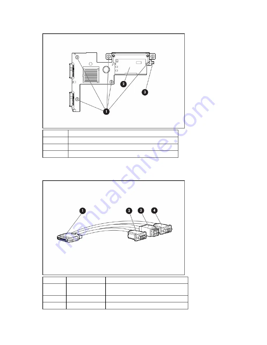
Hard drive backplane components 


Item Description 

Hard drive backplane thumbscrews (5) 

Smart Array E200i Controller cache module 

Internal USB connector 


Local I/O cable 


Item Connector 

Description 

1 Server 

blade 

For connecting to the local I/O cable 

connector on the server blade front panel 

Video 

For connecting a video monitor 

USB  

For connecting up to two USB devices 

Summary of Contents for BL460c - ProLiant - G5

Page 1: ...HP ProLiant BL460c Server Blade Maintenance and Service Guide June 2006 First Edition Part Number 405778 001 ...

Page 2: ...herein Microsoft and Windows are U S registered trademarks of Microsoft Corporation Intel and Pentium are trademarks or registered trademarks of Intel Corporation or its subsidiaries in the United States and other countries Linux is a U S registered trademark of Linus Torvalds June 2006 First Edition Part Number 405778 001 Audience assumptions This guide is for an experienced service technician HP...

Page 3: ...troller cache module 29 HP Smart Array E200i Controller battery pack 30 Server blade handle 31 Release button 32 Heatsink 33 Processor 35 System board 39 System battery 44 Cabling 47 Using the local I O cable 47 Connecting locally to a server blade with video and USB devices 47 Accessing a server blade with local KVM 47 Accessing a server blade with local media devices 48 Diagnostic tools 50 Troub...

Page 4: ...ponents 56 Mezzanine connector definitions 57 FBDIMM slot numbering 57 System maintenance switch 57 Hard drive backplane components 58 Local I O cable 58 Specifications 60 Environmental specifications 60 Server blade specifications 60 Acronyms and abbreviations 61 Index 63 ...

Page 5: ...n will help you over the telephone HP specifies in the materials shipped with a replacement CSR part whether a defective part must be returned to HP In cases where it is required to return the defective part to HP you must ship the defective part back to HP within a defined period of time normally five 5 business days The defective part must be returned with the associated documentation in the pro...

Page 6: ...ine la société de courses ou le transporteur à utiliser Pour plus d informations sur le programme CSR de HP contactez votre Mainteneur Agrée local Pour plus d informations sur ce programme en Amérique du Nord consultez le site Web HP http www hp com go selfrepair Service de garantie pièces seules Votre garantie limitée HP peut inclure un service de garantie pièces seules Dans ce cas les pièces de ...

Page 7: ...imieren und höhere Flexibilität beim Austausch defekter Bauteile zu ermöglichen Wenn HP oder ein HP Servicepartner bei der Diagnose feststellt dass das Produkt mithilfe eines CSR Teils repariert werden kann sendet Ihnen HP dieses Bauteil zum Austausch direkt zu CSR Teile werden in zwei Kategorien unterteilt Zwingend Teile für die das Customer Self Repair Verfahren zwingend vorgegeben ist Wenn Sie ...

Page 8: ...rgo de los gastos de desplazamiento y de mano de obra de dicho servicio Opcional componentes para los que la reparación por parte del usuario es opcional Estos componentes también están diseñados para que puedan ser reparados por el usuario Sin embargo si precisa que HP realice su sustitución puede o no conllevar costes adicionales dependiendo del tipo de servicio de garantía correspondiente al pr...

Page 9: ...eparatie door de klant optioneel is Ook deze onderdelen zijn ontworpen voor reparatie door de klant Als u echter HP verzoekt deze onderdelen voor u te vervangen kunnen daarvoor extra kosten in rekening worden gebracht afhankelijk van het type garantieservice voor het product OPMERKING Sommige HP onderdelen zijn niet ontwikkeld voor reparatie door de klant In verband met de garantievoorwaarden moet...

Page 10: ...a HP exige que um técnico autorizado substitua a peça Essas peças estão identificadas com a marca No Não no catálogo de peças ilustrado Conforme a disponibilidade e o local geográfico as peças CSR serão enviadas no primeiro dia útil após o pedido Onde as condições geográficas permitirem a entrega no mesmo dia ou em quatro horas pode ser feita mediante uma taxa adicional Se precisar de auxílio entr...

Page 11: ...Customer self repair 11 ...

Page 12: ...Customer self repair 12 ...

Page 13: ...Customer self repair 13 ...

Page 14: ...Customer self repair 14 ...

Page 15: ...er blade components Item Description Spare part number Customer self repair on page 5 Mechanical components 1 Access panel 410303 001 Mandatory1 2 Hard drive blank 392613 001 Mandatory1 System components 3 Front panel hard drive cage assembly with front panel LED board 410301 001 Mandatory1 4 Processors ...

Page 16: ...6797 001 Optional2 i 2 33 GHz Intel Xeon processor 5148 dual core 4 MB cache 1066 MHz FSB 431716 001 Optional2 j 2 66 GHz Intel Xeon processor 5150 dual core 4 MB cache 1333 MHz FSB 416798 001 Optional2 k 3 00 GHz Intel Xeon processor 5160 dual core 4 MB cache 1333 MHz FSB 416799 001 Optional2 5 Heatsink 410304 001 Optional2 6 Hard drives a 36 GB SAS SFF 10 000 rpm 376596 001 Mandatory1 b 72 GB SA...

Page 17: ...also designed for customer self repair If however you require that HP replace them for you there may or may not be additional charges depending on the type of warranty service designated for your product 3 No Some HP parts are not designed for customer self repair In order to satisfy the customer warranty HP requires that an authorized service provider replace the part These parts are identified a...

Page 18: ...os por el usuario Sin embargo si precisa que HP realice su sustitución puede o no conllevar costes adicionales dependiendo del tipo de servicio de garantía correspondiente al producto 3 No No Algunos componentes no están diseñados para que puedan ser reparados por el usuario Para que el usuario haga valer su garantía HP pone como condición que un proveedor de servicios autorizado realice la sustit...

Page 19: ...Illustrated parts catalog 19 ...

Page 20: ...ess panel HP Insight Diagnostics software HP Insight Diagnostics on page 50 Safety considerations Before performing service procedures review all the safety information Preventing electrostatic discharge To prevent damaging the system be aware of the precautions you need to follow when setting up the system or handling parts A discharge of static electricity from a finger or other conductor may da...

Page 21: ...tions This symbol indicates the presence of hazardous energy circuits or electric shock hazards Refer all servicing to qualified personnel WARNING To reduce the risk of injury from electric shock hazards do not open this enclosure Refer all maintenance upgrades and servicing to qualified personnel This symbol indicates the presence of electric shock hazards The area contains no user or field servi...

Page 22: ...ote shutdown of applications and the OS before the server blade enters standby mode Press and release the Power On Standby button This method initiates a controlled shutdown of applications and the OS before the server blade enters standby mode Press and hold the Power On Standby button for more than 4 seconds to force the server blade to shut down This method forces the server blade to enter stan...

Page 23: ...NG To reduce the risk of personal injury from hot surfaces allow the drives and the internal system components to cool before touching them CAUTION To prevent damage to electrical components properly ground the server blade before beginning any installation procedure Improper grounding can cause ESD To replace the component 1 Place the access panel on top of the server blade with the hood latch op...

Page 24: ...nk slide the blank into the bay until it locks into place Hard drive To remove the component 1 Determine the status of the hard drive from the hot plug SAS hard drive LED combinations SAS and SATA hard drive LEDs on page 55 2 Back up all server data on the hard drive 3 Remove the hard drive ...

Page 25: ...d drive 2 Install the hard drive FBDIMM CAUTION Use only HP FBDIMMs FBDIMMs from other sources may adversely affect data integrity To remove the component 1 Power down the server blade on page 22 2 Remove the server blade on page 22 3 Remove the access panel Access panel on page 23 ...

Page 26: ... Power down the server blade on page 22 2 Remove the server blade on page 22 3 Remove the access panel Access panel on page 23 4 Remove all hard drives Hard drive on page 24 5 Remove all hard drive blanks Hard drive blank on page 23 CAUTION Remove all hard drives and hard drive blanks before removing the hard drive backplane 6 Remove the hard drive backplane ...

Page 27: ...e 23 3 Install the server blade Front panel hard drive cage assembly To remove the component 1 Power down the server blade on page 22 2 Remove the server blade on page 22 3 Remove the access panel Access panel on page 23 4 Remove all hard drives Hard drive on page 24 5 Remove all hard drive blanks Hard drive blank on page 23 6 Remove the hard drive backplane Hard drive backplane on page 26 ...

Page 28: ...anine card Optional mezzanine cards enable network connectivity and provide Fibre Channel support For mezzanine card locations see the system board components on page 56 To remove the component 1 Power down the server blade on page 22 2 Remove the server blade on page 22 3 Remove the access panel Access panel on page 23 4 Remove the mezzanine card ...

Page 29: ...nstall the server blade HP Smart Array E200i Controller cache module To remove the component 1 Power down the server blade on page 22 2 Remove the server blade on page 22 3 Remove the access panel Access panel on page 23 4 Remove all hard drives Hard drive on page 24 5 Remove all hard drive blanks Hard drive blank on page 23 6 Remove the hard drive backplane Hard drive backplane on page 26 ...

Page 30: ...ent 1 Power down the server blade on page 22 2 Remove the server blade on page 22 3 Remove the access panel Access panel on page 23 4 Remove all hard drives Hard drive on page 24 5 Remove all hard drive blanks Hard drive blank on page 23 6 Remove the hard drive backplane Hard drive backplane on page 26 7 Remove the Smart Array E200i Controller cache module HP Smart Array E200i Controller cache mod...

Page 31: ...Power down the server blade on page 22 2 Remove the server blade on page 22 3 Remove the access panel Access panel on page 23 4 Remove all hard drives Hard drive on page 24 5 Remove all hard drive blanks Hard drive blank on page 23 6 Remove the hard drive backplane Hard drive backplane on page 26 7 Remove the front panel hard drive cage assembly Front panel hard drive cage assembly on page 27 ...

Page 32: ...e server blade on page 22 2 Remove the server blade on page 22 3 Remove the access panel Access panel on page 23 4 Remove all hard drives Hard drive on page 24 5 Remove all hard drive blanks Hard drive blank on page 23 6 Remove the hard drive backplane Hard drive backplane on page 26 7 Remove the front panel hard drive cage assembly Front panel hard drive cage assembly on page 27 ...

Page 33: ...o cool before touching them To remove the component 1 Power down the server blade on page 22 2 Remove the server blade on page 22 3 Remove the access panel Access panel on page 23 4 Remove all hard drives Hard drive on page 24 5 Remove all hard drive blanks Hard drive blank on page 23 6 Remove the hard drive backplane Hard drive backplane on page 26 7 Remove the front panel hard drive cage assembl...

Page 34: ... 1 Clean the old thermal grease from the processor with the alcohol swab Allow the alcohol to evaporate before continuing 2 Remove the thermal interface protective cover from the heatsink CAUTION Heatsink retaining screws should be tightened in diagonally opposite pairs in an X pattern ...

Page 35: ...cessor socket 2 with a processor and a heatsink or a processor cover and a heatsink blank IMPORTANT Processor socket 1 must always be populated If processor socket 1 is empty the server blade does not power up To remove the component 1 Power down the server blade on page 22 2 Remove the server blade on page 22 3 Remove the access panel Access panel on page 23 4 Remove all hard drives Hard drive on...

Page 36: ...36 9 Open the processor retaining latch and the processor socket retaining bracket 10 Using your fingers remove the failed processor To replace the component IMPORTANT Be sure the processor remains inside the processor installation tool ...

Page 37: ...or in the tool 2 Align the processor installation tool with the socket and install the spare processor CAUTION The processor is designed to fit one way into the socket Use the alignment guides on the processor and socket to properly align the processor with the socket Refer to the server blade hood label for specific instructions ...

Page 38: ...tool clicks and separates from the processor and then remove the processor installation tool 4 Close the processor retaining latch and the processor socket retaining bracket 5 Clean the old thermal grease from the heatsink with the alcohol swab Allow the alcohol to evaporate before continuing ...

Page 39: ... retaining screws should be tightened in diagonally opposite pairs in an X pattern 7 Install the heatsink 8 Install the front panel hard drive cage assembly 9 Install the hard drive backplane 10 Install the hard drive blank 11 Install the hard drives 12 Install the access panel Access panel on page 23 13 Install the server blade System board To remove the component ...

Page 40: ...e the hard drive backplane Hard drive backplane on page 26 7 Remove the front panel hard drive cage assembly Front panel hard drive cage assembly on page 27 8 Remove all FBDIMMs FBDIMM on page 25 9 Remove any mezzanine cards Mezzanine card on page 28 10 Remove the heatsink on page 33 11 Open the processor retaining latch and the processor socket retaining bracket 12 Using your fingers remove the p...

Page 41: ... or slide the processor when lowering the processor into the socket CAUTION To avoid damage to the processor Handle the processor only by the edges Do not touch the bottom of the processor especially the contact area 13 Remove the system board assembly To replace the system board 1 Install the spare system board 2 Prepare the processor socket on the spare system board ...

Page 42: ... Install the processor socket cover onto the processor socket of the failed system board 4 Install the processor on the spare system board CAUTION The processor is designed to fit one way into the socket Use the alignment guides on the processor and socket to properly align the processor with the socket Refer to the server blade hood label for specific instructions ...

Page 43: ...lel to the system board to avoid damage to the pins 5 Close the processor retaining latch and the processor socket retaining bracket 6 Clean the old thermal grease from the heatsink and the top of the processor with the alcohol swab Allow the alcohol to evaporate before continuing ...

Page 44: ...ocess and should NOT be modified This option should only be used by qualified service personnel This value should always match the serial number sticker located on the chassis 4 Press the Enter key to clear the warning 5 Enter the serial number and press the Enter key 6 Select Product ID 7 Enter the product ID and press the Enter key 8 Press the Esc key to close the menu 9 Press the Esc key to exi...

Page 45: ...for this product To remove the component 1 Power down the server blade on page 22 2 Remove the server blade on page 22 3 Remove the access panel Access panel on page 23 4 Remove all hard drives Hard drive on page 24 5 Remove the hard drive backplane Hard drive backplane on page 26 6 Remove the front panel hard drive cage assembly Front panel hard drive cage assembly on page 27 7 Remove the system ...

Page 46: ...6 9 Remove the battery IMPORTANT Replacing the system board battery resets the system ROM to its default configuration After replacing the battery reconfigure the system through RBSU To replace the component reverse the removal procedure ...

Page 47: ... cable to connect a monitor and any of the following USB devices USB hub USB keyboard USB mouse USB CD DVD ROM drive USB diskette drive Numerous configurations are possible This section offers two possible configurations Accessing a server blade with local KVM CAUTION Before disconnecting the local I O cable from the connector always squeeze the release buttons on the sides of the connector Failur...

Page 48: ...evices Use the following configuration when configuring a server blade or loading software updates and patches from a USB CD DVD ROM or a USB diskette 1 Connect the local I O cable to the server blade 2 Connect the video connector to a monitor 3 Connect a USB hub to one USB connector 4 Connect the following to the USB hub USB CD DVD ROM drive USB keyboard USB mouse USB diskette ...

Page 49: ...necting a USB diskette drive and or USB CD ROM drive to the server blade The USB hub provides additional connections Item Description 1 Monitor 2 USB CD DVD ROM drive or diskette drive 3 USB keyboard 4 USB hub 5 USB mouse 6 Local I O cable ...

Page 50: ...page Under self help resources select ProLiant Troubleshooting Guide The Technical Documentation website http www docs hp com Select Enterprise Servers Workstations and Systems Hardware and then the appropriate server HP Insight Diagnostics HP Insight Diagnostics is a proactive server blade management tool available in both offline and online versions that provides diagnostics and troubleshooting ...

Page 51: ...g From within HP SIM HP Systems Insight Manager on page 51 From within Survey Utility From within operating system specific IML viewers For NetWare IML Viewer For Windows IML Viewer For Linux IML Viewer Application From within the iLO 2 user interface From within HP Insight Diagnostics on page 50 For more information refer to the Management CD in the HP ProLiant Essentials Foundation Pack Array Di...

Page 52: ...r installation information refer to the HP ISEE Client Installation and Upgrade Guide ftp ftp hp com pub services hardware info isee_client pdf Web Based Enterprise Service WEBES enables administrators to manage hardware events proactively either locally or online The service provides real time multiple event analysis crash analysis and notification locally through SMTP and remotely through ISEE f...

Page 53: ...ions 55 System board components 56 Hard drive backplane components 58 Local I O cable 58 Front panel components Item Description 1 Hard drive bay 1 2 Power On Standby button 3 Local I O connector 4 Hard drive bay 2 5 Server blade handle 6 Release button 7 Serial label pull tab The I O connector and the local I O cable are for some server blade configuration and diagnostic procedures ...

Page 54: ...g Amber Degraded condition Red Critical condition 3 NIC 1 LED Green Network linked Green flashing Network activity Off No link or activity 4 NIC 2 LED Green Network linked Green flashing Network activity Off No link or activity 5 System power LED Green On Amber Standby auxiliary power available Off Off Actual NIC numbers depend on several factors including the operating system installed on the ser...

Page 55: ...active currently Flashing regularly 1 Hz Amber flashing regularly 1 Hz Do not remove the drive Removing a drive may terminate the current operation and cause data loss The drive is part of an array that is undergoing capacity expansion or stripe migration but a predictive failure alert has been received for this drive To minimize the risk of data loss do not replace the drive until the expansion o...

Page 56: ...spare or not configured as part of an array System board components Item Description 1 System board thumbscrew 2 Processor socket 2 3 Processor socket 1 populated 4 Hard drive backplane connector 5 FBDIMMs 8 6 Embedded NICs 2 7 Mezzanine connector 1 Type I mezzanine only shown 8 Battery 9 Mezzanine connector 2 Type I shown or Type II mezzanine 10 System maintenance switch SW2 11 System board thumb...

Page 57: ...s A PCIe x8 mezzanine connector supports x16 cards at up to x8 speeds FBDIMM slot numbering FBDIMM slots Memory bank Memory branch 1 and 3 A 0 5 and 7 B 1 2 and 4 C 0 6 and 8 D 1 System maintenance switch Position Function Default 1 iLO 2 security override Off 2 Configuration lock Off 3 Reserved Off 4 Reserved Off 5 Password disabled Off 6 Reset configuration Off 7 Reserved Off 8 Reserved Off To a...

Page 58: ...thumbscrews 5 2 Smart Array E200i Controller cache module 3 Internal USB connector Local I O cable Item Connector Description 1 Server blade For connecting to the local I O cable connector on the server blade front panel 2 Video For connecting a video monitor 3 USB For connecting up to two USB devices ...

Page 59: ...Component identification 59 Item Connector Description 4 Serial For trained personnel to connect a null modem serial cable and perform advanced diagnostic procedures ...

Page 60: ...atings shown are for sea level An altitude derating of 1 C per 304 8 m 1 8 F per 1 000 ft to 3048 m 10 000 ft is applicable No direct sunlight allowed Upper operating limit is 3 048m 10 000 ft or 70 Kpa 10 1 psia Upper non operating limit is 9 144 m 30 000 ft or 30 3 KPa 4 4 psia Storage maximum humidity of 95 is based on a maximum temperature of 45 C 113 F Altitude maximum for storage corresponds...

Page 61: ...y BBWC battery backed write cache CSR Customer Self Repair ESD electrostatic discharge FBDIMM fully buffered DIMM FC Fibre Channel HBA host bus adapter I O input output iLO 2 Integrated Lights Out 2 IML Integrated Management Log LED light emitting diode NIC network interface controller ...

Page 62: ...CIe peripheral component interconnect express RBSU ROM Based Setup Utility ROM read only memory SAS serial attached SCSI SATA serial ATA SFF small form factor SIM Systems Insight Manager UID unit identification UPS uninterruptible power system USB universal serial bus ...

Page 63: ...d drive backplane 15 26 58 hard drive backplane components 58 hard drive backplane connector 56 58 hard drive backplane thumbscrews 58 hard drive bays 53 hard drive blanks 15 23 hard drive LEDs 55 hard drives 15 24 55 hard drives determining status of 55 hardware kit 15 heatsink 15 33 heatsink blank 15 33 HP Insight Diagnostics 50 I iLO 2 Integrated Lights Out 2 22 IML Integrated Management Log 51...

Page 64: ...erations 20 safety information 20 SAS drives 15 24 55 SAS hard drive LEDs 55 SATA hard drive 15 24 55 SATA hard drive LEDs 55 serial connector 58 serial label pull tab 53 server blade handle 15 31 53 Smart Array E200i Controller components 29 30 specifications server blade 60 static electricity 20 system battery 15 system board 15 39 56 system board thumbscrews 56 system maintenance switch 56 57 T...

Reviews: