


Chapter 3
Preparing Superdome for Booting
Turning On Housekeeping Power and Logging In to the GSP
59
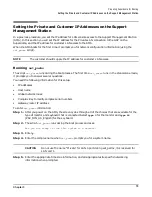
Turning On Housekeeping Power and Logging In to the GSP
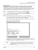
After connecting the serial display device, you are ready to switch on the AC breakers and login to the
Guardian Service Processor (GSP). Switching on the breakers powers up the Bulk Power Supplies (BPS) at
the front of the SPU cabinet, which in turn pr5 V housekeeping (HKP). HKP power distr5 V
power to the logic that requires it.
Before powering up the GSP and SPU cabinet for the first time:
Step 1. Verify that the AC voltage at the input source is within specifications for each cabinet being
installed.
Step 2. Make sure:
•
You are wearing an ESD wrist strap.
•
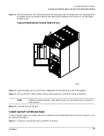
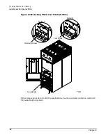
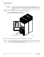
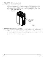
The AC breakers are in the Off position. See Figure 3-23.
•
The cabinet power switch at the front of the cabinet is in the Off position.
•
The AC breakers and cabinet switches on the I/O Expansion Cabinet (if one is present) are in
the Off position.
Step 3. If you have not already done so, power on the serial display device.
The preferred tool is the CE Tool running Reflection 1.
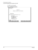
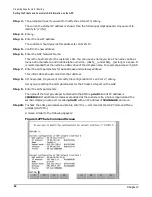
To power up the GSP, set up a communications link, and login to the GSP:
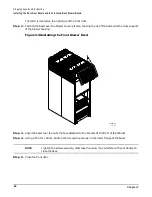
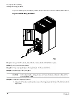
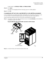
Step 1. Turn on the AC breakers on the Power Distribution Control Assembly (PDCA) (or assemblies, if
there are more than one), at the back of the SPU cabinet.
Power on any other SPU cabinets that were shipped with the system.
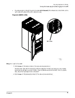
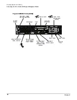
On the front and back panel of a Superdome 32 Way, you should see the HKP (Housekeeping) and
the Present lights illuminate.
Summary of Contents for 9000 Superdome
Page 8: ...Contents 8 ...
Page 9: ...9 Preface ...
Page 21: ...21 IEC 60417 IEC 335 1 ISO 3864 IEC 617 2 International Symbols ...
Page 22: ...22 Figure 9 Superdome Declaration of Conformity Page 1 ...
Page 23: ...23 Figure 10 Superdome Declaration of Conformity Page 2 ...
Page 24: ...24 ...
Page 32: ...Chapter 1 Introduction Installation Warranty 8 ...
Page 130: ...Chapter 4 Verifying and Booting Superdome Enabling iCOD 106 ...
Page 172: ...Appendix A hp Server rx2600 Support Management Station Configuring the SMS 148 ...
Page 184: ...Appendix C Superdome LAN Interconnect Diagram 160 ...
Page 193: ...Appendix F 169 F A180 Support Management Station ...
Page 230: ...Appendix G Connecting Multiple SPU Cabinets Connecting Cables 206 ...
Page 256: ...Appendix H JUST Exploration Tool Error Conditions 232 ...