


Chapter 2
Unpacking and Inspecting
Unpacking the PDCA
26
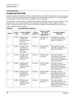
Unpacking the PDCA
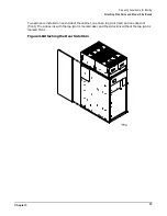
At least one Power Distribution Control Assembly (PDCA) is shipped with the Superdome. In some cases, the
customer may have ordered two PDCAs, the second to be used as a backup power source. Unpack the PDCA
now and ensure it has the power power cord option for your installation.
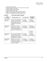
Currently there are several power cord options available for the PDCAs. These are shown in Table 2-1. Only
options 6 and 7 are currently available in new superdome configurations. The other options shown in
Table 2-1 are obsolete but are given in case you encounter a Superdome with obsolete power cord options.
Table 2-2 details options 4 through 7.
Table 2-1
Available Power Options
Option
a
Source
Type
Source Voltage
(nominal)
PDCA
Required
Input Current
Per Phase
200-240 VAC
b
Power Receptacle
Required
1
c
3-phase Voltage
range
200-240 VAC,
phase-to-neutral,
47-63 Hz
(EUR typical)
d
five-wire
25A Maximum
per phase
No receptacle required.
Electrician must hardwire
power to the PDCAb
2
e
3-phase
Voltage range
200-240 VAC,
phase-to-phase,
47-63 Hz
(US typical)
four-wire
44A Maximum
per phase
No receptacle required.
Electrician must hard-wire
power to the PDCAb
4
f
3-phase
Voltage range
200-240 VAC,
phase-to-phase,
47-63 Hz
four-wire
44A Maximum
per phase
Connector and plug
provided with a 2.5-meter
power cable. Electrician
must hard-wire receptacle to
100A site power.b,
g
5
h
3-phase Voltage
range
200-240 VAC,
phase-to-neutral,
47-63 Hz
five-wire
25A Maximum
per phase
Connector and plug
provided with a 2.5-meter
power cable. Electrician
must hard-wire receptacle to
63A site power.b,d
6
3-phase Voltage
range
200-240 VAC,
phase-to-phase,
47-63 Hz
four-wire
44A Maximum
per phase
Connector and plug
provided with a 2.5-meter
power cable. Electrician
must hard-wire receptacle to
60A site power.b,d
7
3-phase Voltage
range
200-240 VAC,
phase-to-neutral,
47-63 Hz
five-wire
25A Maximum
per phase
Connector and plug
provided with a 2.5-meter
power cable. Electrician
must hard-wire receptacle to
32A site power.b,d
Summary of Contents for 9000 Superdome
Page 8: ...Contents 8 ...
Page 9: ...9 Preface ...
Page 21: ...21 IEC 60417 IEC 335 1 ISO 3864 IEC 617 2 International Symbols ...
Page 22: ...22 Figure 9 Superdome Declaration of Conformity Page 1 ...
Page 23: ...23 Figure 10 Superdome Declaration of Conformity Page 2 ...
Page 24: ...24 ...
Page 32: ...Chapter 1 Introduction Installation Warranty 8 ...
Page 130: ...Chapter 4 Verifying and Booting Superdome Enabling iCOD 106 ...
Page 172: ...Appendix A hp Server rx2600 Support Management Station Configuring the SMS 148 ...
Page 184: ...Appendix C Superdome LAN Interconnect Diagram 160 ...
Page 193: ...Appendix F 169 F A180 Support Management Station ...
Page 230: ...Appendix G Connecting Multiple SPU Cabinets Connecting Cables 206 ...
Page 256: ...Appendix H JUST Exploration Tool Error Conditions 232 ...