


Chapter 4
Verifying and Booting Superdome
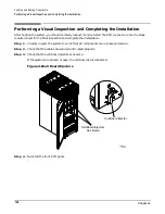
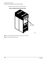
Booting Superdome Partitions
87
Booting Superdome Partitions
Booting Superdome partitions includes the steps listed below. Following this section are detailed procedures
for each of these tasks.
•
Listing the partitions you want to boot
•
Listing the path to each boot device
•
Listing the cell number associated with the core I/O adapter card for the partition
•
Listing the core I/O adapter location for each partition
•
Installing the boot device for the partition (if required)
•
Powering down the cell associated with the core I/O adapter card for the partition
•
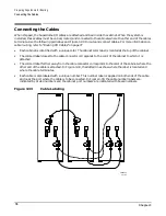
Connecting the boot device cable
•
Powering up the cell associated with the core I/O adapter card for the partition
•
Booting UNIX on the partition
•
Booting the other partitions (if there are others)
NOTE
You can boot as many as eight partitions for each Superdome cabinet. It is easy to lose track of
the partitions you have and have not booted. You need to be organized to boot all of the
partitions in an efficient way. To help you keep track of the partitions you have booted, use the
table on the next page.
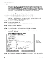
In order to boot the partitions on the Superdome, you need specific values from the boot path for each
Superdome partition. You will use the values you enter in the table to match boot devices to partitions. Refer
to “Determining and Documenting Boot Information” on page 88 to fill in the table. (Feel free to remove the
table from this guide.)
WARNING
Do not mix original cell or Caribe cell boards with within the same partition.
WARNING
Do not mix CPU ASICs (PA8600 vs. PA8700) on either the original or Caribe cell
boards.
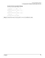
Table 4-1
Boot Information
Partition
Primary
Boot Path
Logical
Cell #
Physical
Cabinet #
of Cell
Physical Cell
Slot # within
Cabinet
Boot Device Adapter Physical Location
Within the PCI Card Cage
Slot #
Cabinet #
I/O Bay #
I/O Chassis #
Summary of Contents for 9000 Superdome
Page 8: ...Contents 8 ...
Page 9: ...9 Preface ...
Page 21: ...21 IEC 60417 IEC 335 1 ISO 3864 IEC 617 2 International Symbols ...
Page 22: ...22 Figure 9 Superdome Declaration of Conformity Page 1 ...
Page 23: ...23 Figure 10 Superdome Declaration of Conformity Page 2 ...
Page 24: ...24 ...
Page 32: ...Chapter 1 Introduction Installation Warranty 8 ...
Page 130: ...Chapter 4 Verifying and Booting Superdome Enabling iCOD 106 ...
Page 172: ...Appendix A hp Server rx2600 Support Management Station Configuring the SMS 148 ...
Page 184: ...Appendix C Superdome LAN Interconnect Diagram 160 ...
Page 193: ...Appendix F 169 F A180 Support Management Station ...
Page 230: ...Appendix G Connecting Multiple SPU Cabinets Connecting Cables 206 ...
Page 256: ...Appendix H JUST Exploration Tool Error Conditions 232 ...