Chapter 4
Removing and Replacing Components
I/O Baseboard Assembly
70
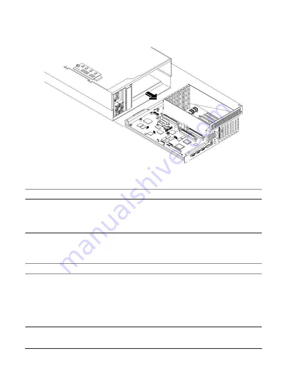
Figure 4-21
I/O Baseboard
Replacing the I/O Baseboard Assembly
NOTE
The I/O baseboard is large, so use care when sliding it into the server chassis.
To replace the I/O baseboard assembly, perform the following steps:
Step 1. Align the I/O baseboard assembly rails with the chassis slots and slide the assembly into the
chassis until it stops against the midplane riser board socket.
CAUTION
Ensure the I/O board locking lever is in the “up” position or the I/O board will hang
up before engaging the midplane riser board socket.
Also, ensure that all fan modules are removed from the chassis prior to sliding in the
I/O baseboard or both the fans and the I/O baseboard may be damaged.
CAUTION
Before installing your replacement I/O board, check dipswitch S5102 on located on
top of the I/O board. Dipswitch position bit 1 must be in the OFF position to disable
the on-board Radeon graphics chip. If you do not disable the Radeon graphics chip it
will appear as “unknown-unclaimed” when performing the
ioscan
command. See
Remember to replace the VGA port cover on the new board that you saved when
removing the old I/O board. This VGA graphics port is not supported on your hp 9000
rp4440 Server.


