b.
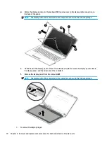
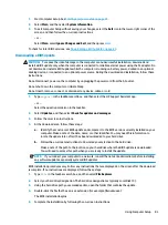
Remove the display bezel (4).
NOTE:
The display will not be connected to the computer as shown in the following image.
2.
To remove the camera/microphone module:
a.
Position the display assembly with the top edge toward you.
b.
Pry up to disengage the camera/microphone module from the adhesive that secures it to the
display (1).
c.
Disconnect the cable (2) from the module.
68
Chapter 6 Removal and replacement procedures for Authorized Service Provider parts
Summary of Contents for 250 G6
Page 1: ...HP 250 G6 Notebook PC Maintenance and Service Guide ...
Page 4: ...iv Safety warning notice ...
Page 8: ...viii ...
Page 14: ...6 Chapter 1 Product description ...
Page 26: ...18 Chapter 2 Components ...
Page 88: ...80 Chapter 6 Removal and replacement procedures for Authorized Service Provider parts ...
Page 106: ...98 Chapter 10 Specifications ...
Page 116: ...108 Chapter 12 Power cord set requirements ...
Page 118: ...110 Chapter 13 Recycling ...


