background image


14 

Appendix A Chassis views and technical 
specifications 

Chassis views 

1420-16G 

Figure 14


1420-16G front panel 


(1) 10/100/1000BASE-T copper ports 

(2) Copper port LEDs 

(3) Power LED  


Figure 15


1420-16G rear panel 


(1) Grounding screw 

(2) AC power receptacle 


1420-24G-2SFP 

Figure 16


1420-24G-2SFP front panel 


(1) 10/100/1000BASE-T copper ports 

(2) 100/1000BASE-X SFP fiber ports 

(3) Copper port LEDs 

(4) Power LED 

(5) Fiber port LEDs 


Summary of Contents for 1420 Series

Page 1: ...HP 1420 Gigabit Ethernet Switch Series Getting Started Guide Part number 5998 5751 Document version 5W100 20141118 5998 5751 ...

Page 2: ...MATERIAL INCLUDING BUT NOT LIMITED TO THE IMPLIED WARRANTIES OF MERCHANTABILITY AND FITNESS FOR A PARTICULAR PURPOSE Hewlett Packard shall not be liable for errors contained herein or for incidental or consequential damages in connection with the furnishing performance or use of this material The only warranties for HP products and services are set forth in the express warranty statements accompan...

Page 3: ... Contacting HP 11 Subscription service 11 Related information 11 Documents 11 Websites 11 Conventions 12 Appendix A Chassis views and technical specifications 14 Chassis views 14 1420 16G 14 1420 24G 2SFP 14 1420 24G 2SFP 10G Uplink 15 1420 24G PoE 124W 15 Technical specifications 16 Chassis dimensions and weights 16 Ports and interface card slots 16 Environmental specifications 16 Power specifica...

Page 4: ...The recommendations do not cover every possible hazardous condition To avoid damage to the electrolytic capacitor in the switch do not store the switch without power for more than one year Before cleaning the switch remove all power cords from the switch Do not clean the switch with a wet cloth or liquid Do not place the switch near water or in a damp environment Prevent water or moisture from ent...

Page 5: ...idity can cause poor insulation electricity creepage mechanical property change of materials and metal corrosion Lasting low relative humidity can cause washer contraction and ESD and cause problems including loose mounting screws and circuit failure High temperature can accelerate the aging of insulation materials and significantly lower the reliability and lifespan of the switch Cleanliness Dust...

Page 6: ... coupling Electromagnetic wave radiation Common impedance including the grounding system coupling To prevent EMI perform the following tasks If AC power is used use a single phase three wire power receptacle with protection earth PE to filter interference from the power grid Keep the switch far away from radio transmitting stations radar stations and high frequency devices Use electromagnetic shie...

Page 7: ...n Figure 1 The 1420 24G 2SFP 1420 24G 2SFP 10G Uplink and 1420 24G PoE 124W switches use Type B mounting brackets as shown in Figure 2 4 Attach the mounting brackets to both sides of the chassis with screws NOTE Mounting brackets are used only for securing the switch to the rack A rack shelf on the rack is used to bear the switch weight Figure 1 Attaching Type A mounting brackets to the switch Fig...

Page 8: ...5 Figure 3 Attaching Type A mounting brackets to the rack post Figure 4 Attaching Type B mounting brackets to the rack post ...

Page 9: ...20 24G PoE 124W Switch Wall mounting Only the HP 1420 16G switch can be installed on a wall The type of screws used to mount the switch on the wall depends on the wall type This section uses a concrete wall as an example The screws must be a minimum of 3 mm 0 12 in and a maximum of 3 8 mm 0 15 in in diameter The screw head must be a minimum of 6 mm 0 24 in and a maximum of 9 8 mm 0 59 in in diamet...

Page 10: ...5 mm 0 06 in between the base of the screw head and the wall anchor so the switch can hang on the screws securely Figure 8 Driving a screw into a wall anchor 4 Align the two mounting holes in the switch chassis bottom with the two screws on the wall and hang the switch Make sure the Ethernet ports are facing upwards or downwards and the chassis side panels are perpendicular to the ground Figure 9 ...

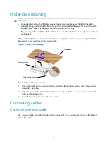
Page 11: ...nting The wall mounting screws provided can be used when you mount the switch under a table Figure 10 Under table mounting To mount the switch under a table 1 Follow the instructions on wall mounting to determine the location of screw holes to be used for under table mounting 2 Align the two mounting holes in the switch chassis bottom with the two screws on the bottom of the table and hang the swi...

Page 12: ...ontact with the slot when the top and bottom spring tabs catch in the slot 3 Remove protective sleeves from optical fibers and the dust plug from the transceiver module 4 Connect the LC connectors of the optical fibers to the transceiver module NOTE Keep the protective sleeves for future use The fiber ports on the HP 1420 24G 2SFP Switch operate in autonegotiation mode For the link between the swi...

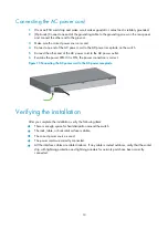
Page 13: ... the AC power outlet 6 Examine the power LED If it is ON the power connection is correct Figure 13 Connecting the AC power cord to the AC power receptacle Verifying the installation After you complete the installation verify the following items There is enough space for heat dissipation around the switch The rack table or horizontal surface is stable The correct power source is used The power cord...

Page 14: ...ng you will receive email notification of product enhancements new driver versions firmware updates and other product resources Related information Documents To find related documents browse to the Manuals page of the HP Business Support Center website http www hp com support manuals For related documentation navigate to the Networking section and select a networking category For a complete list o...

Page 15: ...parated by vertical bars from which you select one choice multiple choices or none 1 n The argument or keyword and argument combination before the ampersand sign can be entered 1 to n times A line that starts with a pound sign is comments GUI conventions Convention Description Boldface Window names button names field names and menu items are in bold text For example the New User window appears cli...

Page 16: ...nified wired WLAN module or the access controller engine on a unified wired WLAN switch Represents an access point Represents a mesh access point Represents omnidirectional signals Represents directional signals Represents a security product such as a firewall UTM multiservice security gateway or load balancing device Represents a security card such as a firewall load balancing NetStream SSL VPN I...

Page 17: ... panel 1 10 100 1000BASE T copper ports 2 Copper port LEDs 3 Power LED Figure 15 1420 16G rear panel 1 Grounding screw 2 AC power receptacle 1420 24G 2SFP Figure 16 1420 24G 2SFP front panel 1 10 100 1000BASE T copper ports 2 100 1000BASE X SFP fiber ports 3 Copper port LEDs 4 Power LED 5 Fiber port LEDs ...

Page 18: ...opper ports 2 1000BASE X SFP 10GBASE SR LR SFP ports 3 Copper port LEDs 4 Power LED 5 Fiber port LEDs Figure 19 1420 24G 2SFP 10G Uplink rear panel 1 Grounding screw 2 AC power receptacle 1420 24G PoE 124W Figure 20 1420 24G PoE 124W front panel 1 10 100 1000BASE T copper ports 1 to 12 are PoE ports 2 PoE status LEDs 3 PoE MAX LED 4 Copper port LEDs 5 Power LED 1 2 3 4 5 ...

Page 19: ...Uplink 44 440 238 mm 1 73 17 32 9 37 in 2 9 kg 6 39 lb 1420 24G PoE 124W 44 440 238 mm 1 73 17 32 9 37 in 3 3 kg 7 28 lb Ports and interface card slots Chassis 10 100 1000BASE T auto sensing Ethernet ports 100 1000BASE X SFP ports 1000BASE X SFP 10GBASE SR LR SFP 1420 16G 16 0 0 1420 24G 2SFP 24 2 0 1420 24G 2SFP 10G Uplink 24 0 2 1420 24G PoE 124W 24 1 to 12 are PoE ports PoE 0 0 Environmental sp...

Page 20: ... power consumption 1420 16G 6 8 W 12 W 1420 24G 2SFP 7 W 18 W 1420 24G 2SFP 10G Uplink 9 5 W 21 W 1420 24G PoE 124W 10 5 W 160 W 124 W PoE Power consumption specifications for PoE switches Chassis Max PoE power per port Max PoE ports at full 30 W output Total PoE output 12 ports Min power consumption Max power consumption including total PoE output 1420 24G PoE 124W 30 W 4 at AC input 124 W at AC ...

Page 21: ...Status Description Steady yellow A 10 100 Mbps link is present Flashing yellow The port is receiving or sending data at 10 100 Mbps Steady green A 1000 Mbps link is present Flashing green The port is receiving or sending data at 1000 Mbps Off No link is present PoE LEDs Table 6 PoE status LED description Status Description Steady yellow The port is supplying power correctly Flashing yellow The por...

Page 22: ... supplies power to the new port Fiber port LEDs Table 8 SFP port LED description Status Description Steady yellow A 100 Mbps link is present Flashing yellow The port is receiving or sending data at 100 Mbps Steady green A 1000 Mbps link is present Flashing green The port is receiving or sending data at 1000 Mbps Off No link is present Table 9 SFP port LED description Status Description Steady yell...

Page 23: ...m Troubleshooting method Power LED off 1 Verify that the correct power source is used and the power cords are correctly connected 2 Verify that the power source side provides power supply correctly LAN interface LED off 1 Verify that the network cable is correctly connected to the network port of the switch 2 Insert the two ends of a network cable into two network ports of the switch If the port L...

Reviews: