background image


HP 1405 Switch Series   

Installation and Getting Started Guide   

HP 1405-5 Switch (J9791A)

HP 1405-5G Switch (J9792A)

HP 1405-8 Switch (J9793A)

HP 1405-8G Switch (J9794A)


Summary of Contents for 1405-5

Page 1: ...HP 1405 Switch Series Installation and Getting Started Guide HP 1405 5 Switch J9791A HP 1405 5G Switch J9792A HP 1405 8 Switch J9793A HP 1405 8G Switch J9794A ...

Page 2: ......

Page 3: ...HP 1405 Switch Series Installation and Getting Started Guide ...

Page 4: ... statements accompanying such products and services Nothing herein should be construed as constituting an additional warranty HP shall not be liable for technical or editorial errors or omissions contained herein Hewlett Packard assumes no responsibility for the use or reliability of its software on equipment that is not furnished by Hewlett Packard Warranty For the latest license and warranty inf...

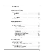
Page 5: ...tch Passes Self Test 2 6 LED Behavior 2 8 3 Mount the Switch 2 8 Wall Mounting 2 8 Horizontal Surface Mounting 2 9 4 Connect the Switch to a Power Source 2 11 5 Connect the Network Cables 2 12 Using the RJ 45 Connectors 2 12 Sample Network Topologies 2 13 3 Troubleshooting Basic Troubleshooting Tips 3 1 Diagnosing with the LEDs 3 3 LED patterns for General Switch Troubleshooting 3 3 Hardware Diagn...

Page 6: ...Specifications A 3 Twisted Pair Cable Connector Pin Outs A 4 Straight through Twisted Pair Cable for 10 Mbps or 100 Mbps Network Connections A 6 Cable Diagram A 6 Pin Assignments A 6 Crossover Twisted Pair Cable for 10 Mbps or 100 Mbps Network Connection A 7 Cable Diagram A 7 Pin Assignments A 7 Straight Through Twisted Pair Cable for 1000 Mbps Network Connections A 8 Cable Diagram A 8 Pin Assignm...

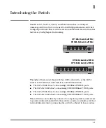
Page 7: ...e 1405 5 Switch has 5 auto sensing 10 100Base TX RJ 45 ports The 1405 5G Switch has 5 auto sensing 10 100 1000Base T RJ 45 ports The 1405 8 Switch has 8 auto sensing 10 100Base TX RJ 45 ports The 1405 8G Switch has 8 auto sensing 10 100 1000Base T RJ 45 ports These switches can be directly connected to computers printers and servers toprovidededicatedbandwidthtothosedevices andyoucanbuildaswitched...

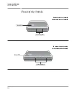
Page 8: ...tch Front of the Switch Front of the Switch 5 4 3 2 1 HP 1405 5 Switch J9791A HP 1405 5G Switch J9792A Power LED Link Activity LEDs 8 7 6 5 4 3 2 1 HP 1405 8 Switch J9793A HP 1405 8G Switch J9794A Power LED Link Activity LEDs ...

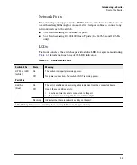
Page 9: ...toring Table 1 1 details the functions of the LED indicators Table 1 1 Switch Status LEDs Switch LEDs State Meaning HP Power LED white On The switch is properly receiving power Off No power connection The switch is NOT receiving power Port LEDs Link Act blue On The port is enabled and receiving a link indication from the connected device Off One of these condition exists no active network cable is...

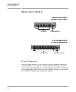
Page 10: ...h and to a power source The external AC DC power adapter supplies 12 volts DC to the switch and automatically adjusts to any AC voltage between 100 240 volts and either 50 or 60 Hz No voltage range settings are required 5 4 3 2 1 8 7 6 5 4 3 2 1 RJ 45 ports DC power connector HP 1405 5 Switch J9791A HP 1405 5G Switch J9792A HP 1405 8 Switch J9793A HP 1405 8G Switch J9794A RJ 45 ports DC power conn...

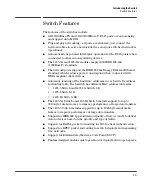
Page 11: ...t devices Automatic learning of the hardware addresses in each switch s address forwarding table Each switch has different MAC address table sizes 1405 5 Switch and 1405 5G Switch 2K 1405 8 Switch 1K 1405 8G Switch 8K The 1405 5G Switch and 1405 8G Switch include support for up to 9216 byte Jumbo frames to improve performance of large data transfers The 1405 5 Switch includes support for up to 204...

Page 12: ...on information for the 1405 5 Switch 1405 5G Switch 1405 8 Switch and 1405 8G Switch Included Parts The switches have the following components Documentation kit Wall table mount accessory kit Four rubber feet Two wall mount tapping screws Two wall mount anchors ...

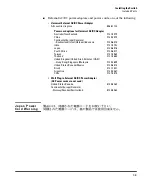
Page 13: ...Denmark Switzerland Israel Vietnam Indonesia India Japan South Africa Taiwan Thailand United Kingdom United Arab Emirates UAE Hong Kong Singapore Malaysia United States Canada Mexico Brazil Argentina Chile 8121 0870 8120 8373 8120 6314 8121 0702 8120 6316 8120 6317 8121 0963 8121 0664 8120 8699 8120 6313 8121 1081 8120 8367 8121 0514 Wall Plug in External AC DC Power Adapter AC Power cords are not...

Page 14: ...the supplied power cord does not fit contact HP networking support When installing the switch the AC outlet should be near the switch and should be easily accessible in case the switch must be powered off Ensure the switch does not overload the power circuits wiring and over current protection To determine the possibility of overloading the supply circuits add together the ampere ratings of all de...

Page 15: ...ome installation precautions 2 Verify the switch passes self test page 2 6 Plug the switch into a power source and observe that the LEDs on the switch s front panel indicate correct switch operation 3 Mount the switch page 2 8 The switches can be mounted on a wall or on a horizontal surface 4 Connect power to the switch page 2 11 Once the switch is mounted plug it into the main power source 5 Conn...

Page 16: ...formation Specifications for more information Installation Location Before installing the switch plan its location and orientation relative to other devices and equipment On the back of the switch leave at least 7 6 cm 3 inches of space for the twisted pair cabling On the back of the switch leave at least 3 8 cm 1 1 2 inches of space for the power cord On the sides of the switch leave at least 7 6...

Page 17: ...k of the switch and then plug the AC DC power adapter into a nearby properly grounded electrical outlet Note The switches are shipped with one of two types of AC DC power adapter either the universal AC DC adapter with an AC power cord or the wall plug in AC DC adapter without an AC power cord Figure 2 1 Connecting the switch power adapter 8 8 7 6 5 4 3 2 1 2 3 4 5 6 7 8 Connect the wall plug in A...

Page 18: ...ower cord displaying the mark of the safety agency that defines the regulations for power cords in your country The mark is your assurance that the power cord can be used safely with the switch If the supplied power cord does not fit contact HP networking support Caution Use only the AC DC power adapter and power cord supplied with the switch Use of other adapters or power cords including those th...

Page 19: ...ting for diagnostic help 3 Mount the Switch After the switch passes self test it is ready to be mounted in a stable location The switch can be mounted in these ways on a horizontal surface on a wall Wall Mounting You can mount the switch on a wall A special kit for wall mounting is included with the switch Caution The switch should be mounted only to a wall or wood surface that is at least 1 2 inc...

Page 20: ...he switch from sliding on the surface Attach the rubber feet to the four corners on the bottom of the switch within the embossed angled lines Use a sturdy surface in an uncluttered area You may want to secure the networking cables and switch power cord to the table leg or other part of the surface structure to help prevent tripping over the cords Caution Ensure the air flow is not restricted aroun...

Page 21: ...2 10 Installing the Switch Installation Procedures Figure 2 4 Horizontal surface mounting ...

Page 22: ...of two types of AC DC power adapter either the universal AC DC adapter with an AC power cord or the wall plug in AC DC adapter without an AC power cord Figure 2 5 Connecting power to the switch 2 Re check the LEDs during self test See LED Behavior on page 2 8 8 8 7 6 5 4 3 2 1 2 3 4 5 6 7 8 Connect the wall plug in AC DC power adapter to the switch and an AC power outlet Connect the universal AC D...

Page 23: ...lug into the RJ 45 port until the tab on the plug clicks into place When power is on for the switch and for the connected device the Link Act LED for the port should light to confirm a powered on device for example an end node is at the other end of the cable If the Link Act LED does not go on when the network cable is connected to the port see Diagnosing with the LEDs in chapter 4 Troubleshooting...

Page 24: ... end nodes printers and other peripherals are directly connected as shown in the above illustration Because the switches have the Auto MDIX feature the connections between the switches and end nodes or servers can be through category 5 straight through or cross over twisted pair cable Category 3 or 4 cable can also be used if the connection is 10 Mbps only 8 7 6 5 4 3 2 1 INTERNET Twisted pair str...

Page 25: ...ays to determine the link speed and the communication mode half duplex or full duplex If the connected device is also configured to Auto the switch will automatically negotiate both link speed and communication mode If the connected device has a fixed configuration for example 100 Mbps at half or full duplex the switch will automatically sense the link speed but will default to a communication mod...

Page 26: ...t cable wiring A category 5 cable tester is a recommended tool for every 100Base TX and 1000Base T network installation Improper Network Topologies It is important to make sure you have a valid network topology Common topology faults include excessive cablelengthandexcessiverepeaterdelaysbetweenendnodes Ifyouhave network problems after recent changes to the network change back to the previous topo...

Page 27: ...D patterns for General Switch Troubleshooting 1 Check in the table for the LED pattern you see on your switch 2 Refer to the corresponding diagnostic tip on the next few pages Table 3 1 LED Error Indicators LED Pattern Indicating Problems Diagnostic Tips Power Port Link Act LED Off with power cord plugged in See Note 1 On Off with cable connected 1 This LED is not important for the diagnosis ...

Page 28: ...ed properly Verify the connected device and switch are both powered on and operating correctly Verify you have used the correct cable type for the connection For twisted pair connections to the fixed 10 100 1000 ports either straight through or cross over cables can be used because of the switch s Auto MDIX feature and the Auto MDI MDI X feature of the 10 100 1000 T port For1000Base Tconnections v...

Page 29: ...10Base T 100Base TX or1000Base Tstandards Thetwisted pair cables attached to the switch must be compatible with the appropriate standards To verify your cable is compatible with these standards use a qualified cable test device Testing End to End Network Communications Both the switch and the cabling can be tested by running an end to end communications test a test that sends known data from one n...

Page 30: ... information Additionally your HP authorized network reseller can provide you with assistance both with services that they offer and with services offered by HP Before Calling Support Before calling your networking dealer or HP Support to make the support process most efficient you first should retrieve the following information Information Item Information Location Product identification On the s...

Page 31: ...m 3 6 in 3 35 cm 1 32 in 0 23 kg 0 5 lbs 1405 8G Switch J9794A 15 5 cm 6 10 in 9 15 cm 3 6 in 3 35 cm 1 32 in 0 23 kg 0 5 lbs AC Voltage AC Input MaximumOutput Current 15W Inline External Adapter P N 5066 1122 100 240 volts 50 60 Hz 1 25A 13WWall PlugExternalAdapter P Ns 5184 5863 and 5184 5864 100 240 volts 50 60 Hz 1 085A DC Voltage DC Maximum Current 1405 5 Switch J9791A 12 volts 0 15A 1405 5G ...

Page 32: ...g connected to any switch Acoustics No fans Safety EN 60950 1 2006 IEC 60950 1 2005 CSA C22 2 No 60950 UL 60950 2 Operating Non Operating Temperature 0 C to 40 C 32 F to 104 F 40 C to 70 C 40 F to 158 F Relative humidity non condensing 15 to 95 at 40 C 104 F 15 to 90 at 65 C 149 F Maximum altitude 3048 m 10 000 ft 3048 m 10 000 ft ...

Page 33: ...ation Near End Crosstalk NEXT and Far End Crosstalk FEXT Additionally unlike the cables for 100BASE TX the 1000BASE T cables must pass tests for Equal Level Far End Crosstalk ELFEXT and Return Loss When testing your cabling be sure to include the patch cables that connect the switch and other end devices to the patch panels on your site The patch cables are frequently overlooked when testing cable...

Page 34: ... cables or crossover cables If you happen to use a correctly wired crossover cable though the switch will still be able to automatically detect the MDI MDI X operation and link correctly to the connected device Note Using Fixed Configurations If the port configuration is changed to any of the fixed configurations though for example 100 Mbps full duplex the port operates as MDI X only and the corre...

Page 35: ... Connector Pin Outs For 100 Mbps connections to the ports use 100 ohm Category 5 UTP or STP cable only as supported by the IEEE 802 3u Type 100Base TX standard For 1000 Mbps connections 100 ohm Category 5e or better cabling is recommended ...

Page 36: ...ps Full Duplex the ports operate as MDI X ports and straight through cables must be then used for connections to PC NICs and other MDI ports Cable Diagram Note Pins 1 and 2 on connector A must be wired as a twisted pair to pins 1 and 2 on connector B Pins 3 and 6 on connector A must be wired as a twisted pair to pins 3 and 6 on connector B Pins 4 5 7 and 8 are not used in this application although...

Page 37: ... ports operate as MDI X ports and crossover cables must be then used for connections to hubs or switches or other MDI X network devices Cable Diagram Note Pins 1 and 2 on connector A must be wired as a twisted pair to pins 3 and 6 on connector B Pins 3 and 6 on connector A must be wired as a twisted pair to pins 1 and 2 on connector B Pins 4 5 7 and 8 are not used in this application although they...

Page 38: ...or A must be wired as a twisted pair to pins 1 and 2 on connector B Pins 3 and 6 on connector A must be wired as a twisted pair to pins 3 and 6 on connector B Pins 4 and 5 on connector A must be wired as a twisted pair to pins 4 and 5 on connector B Pins 7 and 8 on connector A must be wired as a twisted pair to pins 7 and 8 on connector B Pin Assignments For 1000Base T operation all four pairs of ...

Page 39: ...ns may cause harmful interference to radio communications However there is no guarantee that the interference will not occur in a particular installation If this equipment does cause harmful intereference to radio or television reception which can be determined by turning the equipment off and on the user is encouraged to try to correct the interference by one or more of the following measures Reo...

Page 40: ...feature A 4 wiring rules A 4 cables twisted pair connector pin outs A 4 cabling infrastructure 2 5 Clear button location on switch 1 2 connecting the switch to a power source 2 11 console port location on switch 1 2 cross over cable pin out A 7 D description back of switch 1 4 front of switch 1 2 LEDs 1 3 switch 1 1 diagnostic tests 3 5 end to end connectivity 3 5 testing the switch only 3 5 testi...

Page 41: ...pair connector pin outs A 4 twisted pair wiring rules A 4 network devices connecting to the switch 2 12 network ports connecting to 2 12 location on switch 1 3 types of 1 3 non standard network cables effects 3 2 P parts included with the switch 2 1 physical specifications switch A 1 pin outs twisted pair cables A 4 port LEDs normal operation 2 8 ports 10 100Base TX location on switch 1 4 connecti...

Page 42: ...ommunications 3 5 switch operation 3 5 twisted pair cabling 3 5 tips for troubleshooting 3 1 topologies effects of improper topology 3 2 samples of 2 13 troubleshooting 3 1 basic tips 3 1 common network problems 3 1 connecting to fixed full duplex devices 3 1 diagnostic tests 3 5 effects of improper topology 3 2 effects of non standard cables 3 2 testing end to end communications 3 5 testing the s...

Page 43: ...4 Index ...

Page 44: ... herein is subject to change without notice The only warranties for HP products and services are set forth in the express warranty statements accompanying such products and services Nothing herein should be construed as constituting an additional warranty HP will not be liable for technical or editorial errors or omissions contained herein May 2012 Manual Part Number 5998 3081 ...

Reviews: