


WARNING: Do not assemble, install, or operate this equipment without reading ALL of this manual
and the safety precautions and warnings illustrated in this manual.
KDAR Company
Tel: (314) 692-8555
1 Mulch Lane
Fax: (314) 692-8578
St. Louis, MO 63044
Web Site: www.hotmaxtorches.com
Operator’s Manual
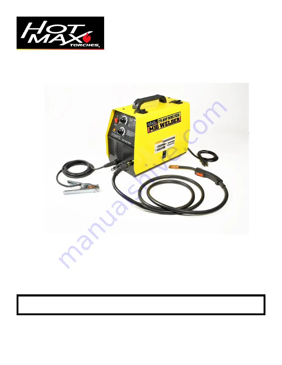
Model 175WFG
Wire Feed Welder
MIG Welders


