horsch 35121253 Operating Instructions Manual Download Page 33

Commissioning


NOTE

These work activities may be carried out only by 

persons trained by HORSCH for this purpose.

WARNING

Increased danger of accidents during commis-

sioning.


¾

Observe the notes in the safety chapter.

Delivery

The machine with implements is normally de-

livered completely assembled on a low loader. 

If parts or modules had to be disassembled for 

transportation purposes, these will be assem-

bled locally by our distributor or field engineer.

Depending on the design of the low loader the 

machine can be unloaded with a tractor, or 

needs to lifted off with suitable lifting gear (forklift 

truck or crane).

Sufficient load bearing capacity of lifting gear 

and lifting tackle must therefore be assured.

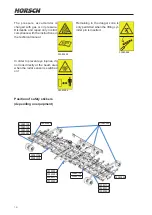
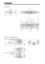
Lifting and lashing points are identified by labels.

When using other lifting points pay careful at-

tention to the centre of gravity and the weight 

distribution. These points must, in any case, only 

be on the frame of the machine. 

Transport

Depending on country-specific regulations and 

working width the equipment can be transported 

on public roads, either attached to a tractor or 

on a trailer or low loader.


¾

The permissible dimensions and weights for 

transport must be complied with.


¾

The tractor must be big enough, so that suffi

-

cient steering and braking abilities are ensured.


¾

If the machine is hitched up in two-point mode, 

the tractor link arms must be blocked against 

swinging sideways.


¾

On a trailer or low loader the machine must be 

secured with tensioning straps or other means.


¾

Attach lifting tackle only at the specially 

marked points.

Installation

Instruction of the operator and initial installation 

of the machine will be carried out by our service 

engineers or distributors. 

The machine can only be released for opera-

tion after the instruction session conducted by 

our service engineer / distributor and after the 

operating instructions have been read.

Any preceding use of the machine is prohibited!

WARNING

Increased danger of accidents during installation 

and maintenance.


¾

Read these operating instructions and become 

acquainted with the machine before starting 

this work.

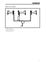
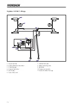
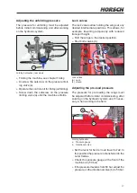
Depending on scope of equipment


¾

Take loosely delivered parts off the machine! 


¾

Check all important screw connections!


¾

Lubricate all grease nipples!


¾

Check air pressure in tyres.


¾

Check all hydraulic connections and hoses 

for correct fastening and function!


¾

Immediately rectify any occurring damage or 

have it corrected!

29

Summary of Contents for 35121253

Page 1: ...READ CAREFULLY PRIOR TO STARTING UP KEEP OPERATING INSTRUCTIONS IN A SAFE PLACE ART 80750202 ISSUE 12 2015 OPERATING INSTRUCTIONS SPRINTER 11 15 NT...

Page 2: ...on refers to conforms with all relevant fundamental health and safety requirements of the EC directive 2006 42 EC For proper implementation of the heath and safety requirements mentioned in the EC dir...

Page 3: ......

Page 4: ......

Page 5: ...r of construction Initial installation Fittings Publication date of Operation Manual 12 2015 Latest change Address of Retailer Name Road Town City Tel Customer No Retailer Address of HORSCH HORSCH Mas...

Page 6: ...plate 19 Design 22 Overview 22 Drill tines 23 Hydraulics 24 Lighting 28 Identification of hydraulic hoses 28 Commissioning 29 Delivery 29 Transport 29 Installation 29 Operation 30 Connecting and trans...

Page 7: ...3...

Page 8: ...the acknowl edgement of receipt to the sales partner This confirms your formal acceptance receipt of the machine The warranty period starts with the date of delivery We reserve the right to alter ill...

Page 9: ...nty claim forms must be submitted to HORSCH through your local HORSCH sales partner Consequential damage The machine has been manufactured by HORSCH with greatest care However despite the intended use...

Page 10: ...d serviced and repaired by persons who are familiar with it and have been made aware of the dangers involved see Qualification of personnel Spare parts Genuine spare parts and accessories from HORSCH...

Page 11: ...ing instructions accessible for the machine operator ensure that the operator has read and under stood the operating instructions Groups of operators Persons who work with the machine must have been t...

Page 12: ...eight For road transport the machine must be set to transport position The machine must have been folded up and secured see chapter Folding and Hitching up and transport position Clean soil from the f...

Page 13: ...ng machine parts are particularly important for safety Hydraulics Brakes if available Connecting features Protective features Lighting If in doubt about the safety relevant status of the machine e g i...

Page 14: ...y the tanks are still preloaded by gas pressure The hydraulic system must be depressurized before maintenance Brake system Depending on the equipment the machines can be equipped with a pneumatically...

Page 15: ...s The following technical limiting values are of particular importance for safety permissible total weight maximum axle loads maximum drawbar load top speed See chapter Technical data type plate and t...

Page 16: ...dverse ly affect the functionality and the operational safety of the machine This can lead to severe or even fatal physical injuries Do not make any structural changes or ex tensions to the machine th...

Page 17: ...point Before cleaning the machine with high pres sure cleaning equipment cover all openings which should stay clear of water steam or cleaning agents for reasons of safety or op eration Do not aim th...

Page 18: ...raulically raised machine parts can lower slowly and unnoticed Failing to pay attention to the danger zone can result in severe or even fatal physical injuries Do not stand under lifted loads Lower su...

Page 19: ...machine 00380054 Before commissioning the machine you should read and follow the op erating instructions 00380055 Watch out for fluids spraying out under high pressure follow the operating instructio...

Page 20: ...o not look directly at the beam area when the radar sensor is switched on 00380894 Position of safety stickers depending on equipment Remaining in the danger zone is only permitted when the lifting cy...

Page 21: ...W Zeichnungsnummer 00380359 Always plug in all hydraulic lines Otherwise components could be damaged because of interconnected hydraulic functions Alle Hydr Leitungen anschlie en ed Sept 03 Datum Entw...

Page 22: ...60 15 5 Load index 140 A8 Working speed km h 7 10 7 10 Required power kW PS 210 235 285 320 260 295 350 400 Double acting control units 3 3 Pressureless return flow max 5 bar 1 1 max system pressure...

Page 23: ...The type plate with the CE marking is located on the frame of the machine Data on the type plate Serial number Permissible total weight Drawbar load DL Axle load Machine type Year of construction 0 1...

Page 24: ...Sprinter 11 NT Sprinter 11 NT with SW 12000 SD 5760 6290 6700 2480 10500 10800 9400 2700 10240 12350 3700 3660 6600 4290 20...

Page 25: ...Sprinter 15 NT 5820 2520 6280 6700 Sprinter 15 NT with SW 12000 SD 5550 6600 14700 15000 14120 3450 12350 4290 21...

Page 26: ...verview 1 3 2 4 6 7 5 Sprinter 15 NT with seed wagon SW 12000 SD 1 Front support wheels 2 Rubber mounting 3 Drill tines three rows 4 Rear support wheels 5 Lighting 6 Seed boxes 7 Folding limit folding...

Page 27: ...s from the seed rows creates a furrow for a deep seed horizon The roller guides the tine in the desired depth shapes an open furrow compacts the seed Principle of open furrow Although the seed is plac...

Page 28: ...le machine parts Observe the notes on hydraulics and pressure accumulator in chapter Safety and responsibility CAUTION Always plug in all hydraulic lines Otherwise components may get damaged because o...

Page 29: ...Sprinter 15 NT Lift Lower 1 Lift lower connections 2 Hydraulic cylinder Lift Lower 3 Double acting lock valve 1 2 3 25...

Page 30: ...connections 3 Pressure gauge 4 Pressure relief valve 5 Check valve 6 3 way rotary valve 7 2 2 directional valve 8 Pressure reducing valve 9 Ball valves 10 Pressure accumulator 11 Hydraulic cylinder fo...

Page 31: ...s allows for example travelling temporarily with reduced transport height Fold the wings to the desired position Shut both valves b a b b Lock valves a open b closed Adjusting the pre load pressure Th...

Page 32: ...arth 4 R green Indicator right 5 58 R brown Rear light right 6 54 red Brake light 7 58 L black Rear light left WARNING Traffic accidents caused by defective lighting Check the lighting before setting...

Page 33: ...low loader The permissible dimensions and weights for transport must be complied with The tractor must be big enough so that suffi cient steering and braking abilities are ensured If the machine is h...

Page 34: ...ING Danger of road accidents caused by losing the machine or machine parts Check all interlocks before starting to drive NOTE Make sure before driving on public roads that the machine meets all respec...

Page 35: ...e manoeu vring range of the machine NOTE Always park the machine on level and solid ground in transport or working position The drill should be parked indoors or under a roof so that no moisture can a...

Page 36: ...d Position Road Folding NOTE During folding operations reduce the control unit before the machine components reach the stop position Clean the folding area and folding cylinders from picked up soil Cl...

Page 37: ...re load The three rows of tines are each connected to a hydraulic cylinder via push rods The tines are thereby pre loaded hydraulically on the rubber elements a b a Bracket for aluminium clips not nee...

Page 38: ...ver a in the recess and unlock the teeth against the spring b c Adjust the rollers to the desired height levels III to III and remove the lever again b The distance from the tip of the tine to the rol...

Page 39: ...ad after completing the field work Position Control unit Floating position Locked position Supply Folding ed Nov06 Datum Entw Dateiname Zeichnungsnummer Maschine Zeichnung Aufkleber 00110681 7 0011068...

Page 40: ...At the same time the seed quantity can be placed and compared with the simulation speed at different fan rotation speeds NOTE Check all settings in the field and the drilling depth before starting wo...

Page 41: ...bers inform about the order In cases of an alarm these sensor numbers help when troubleshooting the hoses Hose installation The outlets on the seed boxes are allocated to the individual coulters throu...

Page 42: ...2 29 28 27 26 25 36 7 8 9 10 11 12 35 34 33 32 31 30 1 2 3 4 5 6 24 23 22 21 20 19 18 13 14 15 16 17 1 36 35 34 33 32 31 30 29 28 27 26 25 24 23 22 21 20 19 18 17 16 15 14 13 12 11 10 9 8 7 6 5 4 3 Di...

Page 43: ...39 40 41 42 43 24 37 31 60 59 58 57 56 55 54 53 52 51 50 49 48 47 46 45 44 43 42 41 40 39 38 37 36 35 34 33 32 Direction of travel 1 2 3 4 5 6 7 8 9 10 11 12 13 14 15 16 17 18 19 20 21 22 23 24 25 26...

Page 44: ...wheels are lifted over approx 20 cm Pre load too high Reduce pre load see chapter Adjusting the working depth Placement depth too low tines not quiet in the soil Pre load too low Increase pre load se...

Page 45: ...r the metering unit so that entered water can flow off Clean the cell wheel inside the metering unit with a brush and compressed air Blow out coulters seed lines seed hopper metering unit and fan with...

Page 46: ...t use soap and water if contaminated Storage If the machine is to be shut down for a longer period of time If possible store the machine under a roof Completely empty and clean the seed and fertiliser...

Page 47: ...eplace if necessary In use Drill tines Wear tip Check for wear Daily When replacing them tighten the screws with 200 Nm each see section Drill tines Hydraulics Hydraulic system and components Check al...

Page 48: ...on the crimp sleeve year month and the hose quarter year Crimp sleeve Hose Depending on the conditions of use e g weather influences or in case of higher strains on the machine the hoses may need to b...

Page 49: ...6 1 8 9 10 4 6 1 00 5 5 6 8 10 4 15 3 17 9 7 1 00 9 3 11 5 17 2 25 30 8 1 25 13 6 16 8 25 37 44 8 1 00 14 5 18 27 40 47 10 1 50 26 6 33 50 73 86 10 1 25 28 35 53 78 91 12 1 75 46 56 86 127 148 12 1 2...

Page 50: ...31 2 35 2 44 7 50 2 7 16 11 1 33 9 36 6 50 2 55 6 70 5 78 6 1 2 12 7 47 5 54 2 77 3 86 8 108 5 122 0 9 16 14 3 67 8 81 3 108 5 122 0 156 0 176 3 5 8 15 9 95 0 108 5 149 1 169 5 216 0 244 0 3 4 19 1 1...

Page 51: ...e disposal of auxiliary and operating me dia as well as other chemicals you must strictly comply with the specifications in the respective safety data sheets Decommissioning If the machine is no longe...

Page 52: ...Delivery 29 Drill tines 23 E Environment 47 F folding 32 Folding 32 Foreword 4 G Groove spacing 18 H Hose installation 37 Hydraulics 10 24 43 44 I Installation 29 L Liability 4 Lift 33 Lighting 28 43...

Page 53: ...Storage 42 T Technical data 18 Top speed 8 Traffic 8 Transport 8 29 Transport height 18 Transport position 30 Transport width 8 18 Troubleshooting 40 Type approval 8 Type plate 19 Tyres 18 U Unfoldin...

Page 54: ......

Page 55: ...chnical specifications and pictograms are approximate and for information only Subject to technical product revisions HORSCH Maschinen GmbH Sitzenhof 1 92421 Schwandorf Tel 49 94 31 7143 0 Fax 49 94 3...

Reviews: