User manual
PS3016
16 Port Layer 2 PoE Switch
Page 1: ...User manual PS3016 16 Port Layer 2 PoE Switch...
Page 2: ...wing chapters Chapter 1 Product Introduction Briefly describes the basic features Detailed hardware software specifications of the switch and the appearance details Chapter 2 Product Installation Guid...
Page 3: ...re used providing flexible cost effective full Gigabit access and uplink ports complete security mechanisms improved ACL QoS strategy and rich VLAN capabilities It is easy to manage and maintain meet...
Page 4: ...parating 1 8 ports from each other can effectively restrain network storm and improve network performance AI Extend mode Designed for monitoring application scenarios 1 8 ports support 250 meters long...
Page 5: ...rts 210 100 1000Mbps RJ45ports 2 Gigabit SFP ports 1 Console port PoE 16 10 100Mbps RJ45 port support PoE Max 150W Single port max 46W LEDs 18 Link Act LEDs 16 POE LEDs 1 Power LED 1 SYS LED Performan...
Page 6: ...thernet IEEE 802 3z 1000BASE X gigabit Ethernet fiber IEEE 802 3ad comply link aggregation standard IEEE 802 3x flow control IEEE 802 1p About the traffic priority of the second layer of Qos Cos proto...
Page 7: ...earning and aging automatically Support static dynamic filter address table Safety Password protection Support based on the port number IP address MAC address restrictions on user access Support HTTPS...
Page 8: ...acket filtering function Support port mirroring port redirection flow rate limit QoS re marking QoS Support 8 port queue Support port priority 802 1p priority DSCP priority Support SP RR WRR WFQ Prior...
Page 9: ...suppression Link aggregation Support static aggregation Support dynamic aggregation Support IP MAC hybrid load balancing mode Supports up to 32 aggregation groups IPv6 Support IPv6 Ping IPv6 Tracert I...
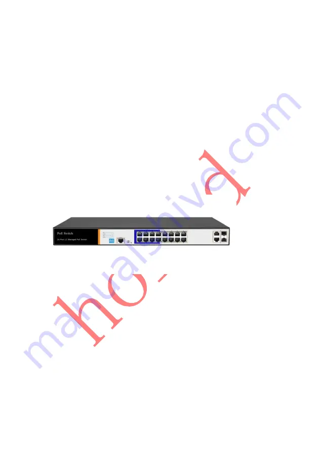
Page 10: ...port Ping Tracert detect cable testing 1 4 Appearance Front Panel Including indicators RJ45 port DIP switch RST button SFP port CONSOLE port as shown below indicator PS3016S The indicator working stat...
Page 11: ...corresponding RJ45 port is connected to the powered device and the power supply is normal Off The corresponding RJ45 port is not connected to the powered device or the power supply is abnormal LINK AC...
Page 12: ...work Extend 1 8 port rate down to 10Mbps but the transmission distance up to 250 meters VLAN Isolating ports 1 8 from each other suppress network storms effectively and improve network performance AI...
Page 13: ...and enter the restarting state When the SYS lamp restarts the device restarts When the switch is powered on press and hold the button for more than 5s to release the button and enter the reset state W...
Page 14: ...ing strikes and extend product life Chapter2 Hardware connection 2 1 RJ45 port connection Connect the RJ45 port of the switch and the corresponding network device via cables the POE power supply funct...
Page 15: ...ossover cable can be used for Ethernet connection Do not connect the RJ45 port to the phone line 2 2 SFP Port connection PS3016S SFP port only support Gigabit fiber module Recommended use of standard...
Page 16: ...f the light is off the link is failure please check the line to confirm that the corresponding equipment is enabled Note DO NOT excessive bending fiber the radius of curvature should not be lessthan 1...
Page 17: ...s normally Port LEDs indicates the connection status of each port indicating that the switch has started to work normally Chapter3 Installation 3 1 Installation Precautions Note To avoid improper use...
Page 18: ...it with liquid Temperature and humidity To ensure the long term stability working of the switch please maintain a certain temperature and humidity environment High or low humidity easily lead to leak...
Page 19: ...ent static electricity from affecting the normal operation of the equipment please note the following 1 Regular dust keep the indoor air clean 2 Make sure the equipment is well grounded to ensure smoo...
Page 20: ...in good contact with the earth 3 Reasonable wiring to avoid the internal sense ray 4 Outdoor wiring it is recommended to use the signal lightning protection device Installation desk requirement Regard...
Page 21: ...allation steps are as follows 1 Check rack grounding and stability 2 Install the two L brackets in the accessory on each side of the switch panel and secure with the screws provided in the accessory 3...
Page 22: ...round wire properly installed Installation equipment within the rack from the bottom up to avoid overload installation Avoid placing other heavy objects on switch to avoid accidents Ensure heat dissip...
Page 23: ...22 Step2 Manually changed the computer IP address to 192 168 254 X X is 2 254 subnet mask is 255 255 255 0 Step3 Open computer s browser type 192 168 254 1 in the address box hit the Enter key...
Page 24: ...Step4 Enter the default username and password admin and then click Login Step5 Entered the switch web management interface successfully when you see picture as below you can begin to configure the swi...
Page 25: ...ot open the product casing 2 Pay attention to the danger of strong electricity and safe protection when the product is powered on 3 Please select the correct power adapter to supply power to the switc...
Page 26: ...00 meters by using Category 5 or above wires 10 When connecting a switch to multiple PDs be careful not to exceed the maximum output power of the switch POE 11 It is recommended to use the switch indo...