HORA MC250/230 Operating Manual Download Page 7

2 Product Specification

Linear actuators MC250 • MC253 • MC500 • MC503
Operating Manual

Version 2.1 - March 2011

7

2.2

Accessories

2.3

Operating modes

The linear actuator can be operated in Manual or Automatic mode.

The lift is adjusted via the handwheel in Manual mode.

The lift is electrically controlled in Automatic mode.

2.3.1

Continuous mode

In Continuous mode the position of the linear actuator is specified by the system 
control. The input signal (Y) from the system control in the linear actuator is 
continually compared with the output signal (X) from the linear actuator for this 
purpose. The output signal is dependent on the position of the linear actuator 
(travel) in this instance.
The linear actuator moves until the input signal and the output signal correspond.

111

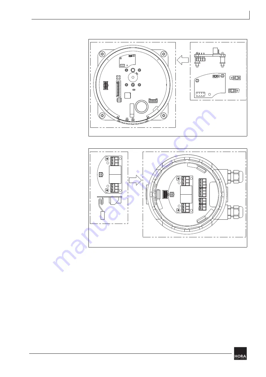
Printed circuit board for output signal X=0/4 … 20 mA

Diagram 2

Printed circuit board for mA output signal on the motherboard 

106

Way-switch printed circuit board  

Diagram 3

Way-switch printed circuit board in cover

0...20 mA

4...20 mA

111

LED1

LED2

LED2

LED1

106

Summary of Contents for MC250/230

Page 1: ...March 2011 111207 EN Operating Manual Linear Actuators MC250 24 MC250 230 MC253 24 MC253 230 MC500 24 MC500 230 MC503 24 MC503 230...

Page 2: ...re compliant with the current state of information at the time of development and are not subject to modification service They must be applied by the operator at his own responsibility in their latest...

Page 3: ...mbly 12 4 1 Check the scope of supply 12 4 2 Prepare for installation 12 4 3 Mount linear actuator on valve 13 4 4 Fit remove cover 14 4 5 Connect the electrics 15 4 5 1 Control independent switching...

Page 4: ...f the above type designation with the linear actuator rating plate must be checked prior to starting any operations in order to guarantee utilisation in accordance with specification The data on the r...

Page 5: ...t First Aid training Work in a safe manner and refrain from any working practice which endangers the safety of persons or damages the linear actuator or other assets in any way whatsoever 1 4 Prior to...

Page 6: ...ng piece 4 Union nut 5 Spindle nut 8 Position display 10 Protective tube 11 Spacer sleeve 13 Bridge 16 Gear casing 33 Sheeting 34 Knob 36 Hand wheel 47 Viewing window This component is available as a...

Page 7: ...e system control The input signal Y from the system control in the linear actuator is continually compared with the output signal X from the linear actuator for this purpose The output signal is depen...

Page 8: ...herboard are bridged in Normal mode If the circuit between B1 and B2 is broken the linear actuator stores the actual position and then moves automatically to its limit position All other control signa...

Page 9: ...in Continuous mode the linear actuator moves to the limit position set by coding switch S7 Open circuit detection is displayed via the green LED in the 47 viewing window Table 7 Green LED display on p...

Page 10: ...Autopause on page 24 2 4 10 Potential free way switch optional extra The optional way switch printed circuit board 106 can be used to set two lift positions at which a potential free electrical conta...

Page 11: ...complete actuating unit in a dry place Observe the transportation and storage temperature of 20 to 65 C Input signal Y Input resistor resistance of load 0 10 V DC 77 k 2 10 V DC 77 k 0 20 mA 510 4 20...

Page 12: ...is complete 4 Report any missing or damaged products to the manufacturer 4 2 Prepare for installation ATTENTION Damage due to valve not being fitted If the linear actuator is operated without valve t...

Page 13: ...ve the blank 314 flange Diagram 6 on page 13 2 Remove the bolt 315 from the coupling 3 or force it out Assembly of MC250 24 MC250 230 MC500 24 and MC500 230 Assembly of MC253 24 MC253 230 MC503 24 and...

Page 14: ...the bolt 315 can be refitted 10 Fit the blank 314 flange Proceed as follows to dismantle the linear actuator 1 Carry out the installation sequence steps in reverse order 4 4 Fit remove cover The termi...

Page 15: ...201 Use a screwdriver 34 to turn the rotary know clockwise through 90 as far as the stop 4 5 Connect the electrics WARNING Danger of death if carried out by unqualified personnel Connection of the el...

Page 16: ...e the cover on page 14 2 Feed the cable through the screw connector in the cover to the terminal strip 3 Connect the electrics in accordance with the circuit diagram Diagram 8 on page 16 Hint The circ...

Page 17: ...positions on page 22 5 7 Set limit position on page 25 Terminal Description UB N1 Supply voltage 2 Control voltage for downward movement in Three point mode 3 Control voltage for upward movement in Th...

Page 18: ...Insert a screwdriver into a groove in the cover 201 and lift the 201 cover out 2 Insert a small screwdriver into the groove provided in the printed circuit board cover for this purpose 33 and remove...

Page 19: ...on 1 Open the linear actuator 201 cover 4 4 Fit remove cover on page 14 2 Press the way switch printed circuit board 106 onto the terminal board 27 using the 107 three spacers 3 Place the plug connect...

Page 20: ...s power supply Secure against unauthorised switching on 1 Open the cover 201 and remove the printed circuit board cover 481 4 4 Fit remove cover on page 14 4 5 2 Remove printed circuit board cover on...

Page 21: ...umper JP1 Jumper right 0 20 mA Jumper left 4 20 mA JP1 Jumper 27 Spacers 110 Main board 111 Printed circuit board for mA output signal 113 Plug in bridge Diagram 13 Installation of the printed circuit...

Page 22: ...ters are set 116 on the coding switches The coding switches are located under the printed circuit board cover 33 in the actuator casing 1 4 4 Fit remove cover on page 14 4 5 2 Remove printed circuit b...

Page 23: ...ic curve S4 Input signal Y 0 10 V DC or 0 20 mA Input signal Y 2 10 V DC or 4 20 mA S5 Actuating time 2 5 s mm Actuating time 5 s mm S6 Autotest and Autopause on Autotest and Autopause off S7 Limit po...

Page 24: ...raverse is triggered approx every 10 days in Autotest A new zero balance is carried out automatically A 3 second pause 2 minute measuring cycle is carried out in Autopause after more than 20 actuator...

Page 25: ...e Proceed as follows to set a way switch 1 Ensure that the linear actuator has been started up and initialised 5 10 Commissioning on page 28 5 9 Initialise the path measuring system on page 27 ATTENTI...

Page 26: ...itch 1 LED 1 indicates the switching status Use potentiometer P2 105 P2 to set way switch 2 LED 2 indicates the switching status 5 Observe the permitted way switch contact load 6 Switch off the power...

Page 27: ...can be triggered in two ways Proceed as follows to initialise via the initialising button WARNING Electric shock due to live components Once the power supply has been switched on there is risk of elec...

Page 28: ...is correctly fixed and the linear actuator cover is closed 4 4 Fit remove cover on page 14 4 Ensure that the linear actuator is switched to Automatic mode 6 1 Switching between Manual and Automatic mo...

Page 29: ...to switch to Manual mode 1 Move the handwheel 36 into the manual mode position and rotate it until the handwheel locks ATTENTION Risk of damage to valve and actuator in Manual mode The valve can get d...

Page 30: ...inuously actuator awaits drive command Standard Operation Actuator carries out drive command Short long rhythm Open circuit detection In operating modes 2 10 V DC or 4 20 mA the input signal has dropp...

Page 31: ...g 5 9 Initialise the path measuring system on page 27 10 1 Troubleshooting If the linear actuator does not work perfectly proceed as follows to eliminate the fault 1 Check that the linear actuator was...

Page 32: ...ta recalculate and change connecting cables if necessary Mains power fluctuations greater than permissible tolerance 2 5 Technical data on page 10 Improve mains power ratios 3 Linear actuator cuts out...

Reviews: