Honeywell V7335A 2000 Series Instruction Sheet Download Page 1

INSTRUCTION SHEET

1

MU1R-9050 0507R10-NE

Subject to change without notice. All rights reserved.

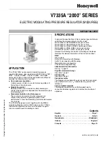
V7335A “2000” SERIES

ELECTRIC MODULATING PRESSURE REGULATOR (MODUREG)

APPLICATION

The V7335 ”2000” series electric modulating pressure 
regulator (Modureg), when installed on V4400/V4400, VK41../
VK81.., V(R)46../V(R)86.., V(R)49../V(R)89.. and V4085 
series gas controls, expands their application versatility and 
provides the following extra functions:

••••

Servo pressure regulation

Outlet pressure is held at a constant value regardless of 

fluctuations of input pressure.

••••

Modulating control

Between minimum and maximum outlet pressure gas 

supply to the appliance is dependent on the electrical signal 
to modulating coil.

Mechanical limitation of outlet pressure

The minimum and maximum burner pressures are 

mechanically adjusted to guarantee good burner 
performance in case the modulating control should become 
out of range.

The V7335 is designed to work together with the W9335 
modulating Modureg control, W4115 logic control, T7335A 
thermistor temperature sensor and an advanced range of 
micro computer based modulating controls.

SPECIFICATIONS

In general the specifications of the concerned gas controls are 
valid. See the corresponding instruction sheet:
MU1R-9003 for V4400/V8800 series gas controls
MU1R-9020 for V4600/V8600 series gas controls
MU1R-9043 for V(R)49../V(R)89.. series gas controls
MU1R-9082 for VR46../VR86.. series gas controls
EN1R-9162 for VK41../VK81.. series gas controls
However the following information is deviating and replaces 
therefore the relevant information of that instruction sheet.

Model

Gas controls:
Suffix M: fast opening with Modureg.
Suffix N: slow opening with Modureg.
Modulating pressure regulator: 
V7335A low voltage Modureg

Adjustment points and dimensions

See fig. 1. page 13

Regulator output pressure range

See table 1. page 2

Electrical rating

See table 2. page 2

Electrical connection

The Modureg is provided with quick connect terminals which 
are suitable for 6.3 mm (

1

/

4

”) receptacles (e.g.series “250” 

fasteners).

Pressure feedback connection

The Modureg regulator has an M5 threaded hole for 
connection between regulator and combustion chamber of 
appliance.

Contents

English . . . . . . . . . . . . . . . . . . . . . . . . . . . . . . . . . . . . Page 1

Deutsch  . . . . . . . . . . . . . . . . . . . . . . . . . . . . . . . . . . .Seite 3

Nederlands . . . . . . . . . . . . . . . . . . . . . . . . . . . . . Bladzijde 6

Italiano  . . . . . . . . . . . . . . . . . . . . . . . . . . . . . . . . . . Pagina 8

Français . . . . . . . . . . . . . . . . . . . . . . . . . . . . . . . . . . Page 10

Summary of Contents for V7335A 2000 Series

Page 1: ...sensor and an advanced range of micro computer based modulating controls SPECIFICATIONS In general the specifications of the concerned gas controls are valid See the corresponding instruction sheet MU1R 9003 for V4400 V8800 series gas controls MU1R 9020 for V4600 V8600 series gas controls MU1R 9043 for V R 49 V R 89 series gas controls MU1R 9082 for VR46 VR86 series gas controls EN1R 9162 for VK41...

Page 2: ...r any adjustment cap is mounted In applications with pressure feedback mount cap and O ring The minimum pressure setting must first be adjusted to ensure that burner will safely light up then maximum pressure setting can be adjusted Any adjustment of minimum pressure setting influences maximum pressure setting Adjusting minimum pressure setting see fig 1 Disconnect pressure feedback connection if ...

Page 3: ...sure setting means of control Mechanical setting of Modureg will prevent too low setting Increase the current until desired pressure is obtained by using pressure setting means of modulating control Mount cap and O ring and reconnect pressure feedback connection if applicable Checkout After any adjustment set appliance in operation and observe through a complete cycle to ensure that burner system ...

Page 4: ... Falls der Heizgerätehersteller oder der Anlagebauer Prüfung Wartung oder Serviceanweisungen heraus gegeben hat sind diese sorgfältig zu befolgen Sind diese nicht vorhanden bitte folgende Richtlinien zu beachten Vor den Einstellungen muss sich der Druck stabilisiert haben Es wird empholen den Modureg zuerst mehrmaligen Betriebsbedingungen auszusetzen um den richtigen Einstellungen zu gewährleisten...

Page 5: ...eder an den Stromkreis an Vermeiden Sie ein Verbiegen der Spule durch eine zu straff verlegte Verdrahtung Einstellung der Zwischendruckstufe Gewisse Steuermodule wie das W9335 ermöglichen sowohl Modulation wie auch feste Einstellungen Bei Einstellung eines Zwischendruckbereich müssen die Anleitungen des Herstellers für die Justierung des betroffenen Steuermoduls unbedingt eingehalten werden Dies b...

Page 6: ...for V4600 V8600 series MU1R 9039 for V4085 servo beveiligingsafsluiters MU1R 9043 for V R 49 V R 89 series EN1R 9052 voor W9335A elektronische besturingseenheid EN1R 9054 voor T7335 elektronische temperatuuropnemer EN1R 9064 voor W9335B tweevoudige elektronische besturingseenheid MU1R 9082 voor VR46 VR86 series EN1R 9162 voor VK41 VK81 series Type Typenummers gasregel en beveiligings afsluitercomb...

Page 7: ...sklep en controleer de uitlaatdruk die door de drukmeter wordt aangegeven Als deze druk moet worden bijgesteld doe dit dan door met een 9 mm steeksleutel de instelschroef voor de minimumuitlaatdruk te verdraaien Rechtsom draaien doet de minimumuitlaatdruk stijgen linksomdraaien doet de minimumuitlaatdruk dalen Controleer of de hoofdbrander vlot rustig en veilig ontsteekt bij de ingestelde minimumd...

Page 8: ... gedurende tenminste een complete bedrijfscycles zodat u er zeker van bent dat het brandersysteem correct functioneert Onderhoud Het is aan te bevelen om de minimum en maximum uitlaatdruk periodiek te kontroleren en deze zonodig opnieuw in te stellen V7335A SERIE 2000 OPERATORE ELETTRICO MODULANTE APPLICAZIONE Il montaggio dell operatore elettrico modulante V7335 serie 2000 sulla valvola gas delle...

Page 9: ...il coperchio e O ring Regolare in primo luogo la pressione minima perché il bruciatore si accenda senza pericolo in seguito regolare la pressione massima La regolazione della pressione minima influisce sulla regolazione della pressione massima Regolazione della pressione di minima vedi fig 1 Staccare la connessione della pressione di reazione se c è Collegare un manometro adatto al condotto o alla...

Page 10: ...ttare che il manometro segni una pressione d uscita Assicurarsi che il Modureg sia collegato al circuito Mettere il sistema nella disposizione fissa Regolare usando il dispositivo di regolazione della pressione la corrente più bassa necessaria per ottenere la pressione più bassa Il sistema meccanico del Modureg impeidirà di determinarne una troppo bassa Aumentare usando il dispositivo di regolazio...

Page 11: ...bre de combustion Pression maximale de fonctionnement La valeur de la pression maximum indiquée sur le bloc gaz est la pression maximum à la quelle le bloc gaz fonctionne en toute securité Cependent la pression maximum de fonctionnement est limitée par la gamma de pression du régulateur concerné c est à dire 30 mbar pour gamma de pression 1 5 14 5 mbar 30 mbar pour gamma de pression 1 5 20 mbar 45...

Page 12: ... et attendre jusqu à ce que l on enregistre une pression de sortie à la jauge de pression Pousser doucement vers l axe jusqu à la butèe vis de réglage maximum et le maintenir en vue de réglage de pression maximale et vérifier la pression à la jauge de pression Si la pression minimale doit être réglée utiliser une clé de 7 mm pour tourner l écrou de réglage en vue d un réglage de la pression maxima...

Page 13: ...ef 7 mm voor maximumuitlaatdruk D Instelschroef 9mm voor minimumuitlaatdruk E O ring F 6 3 mm AMP opschuifstekers G M5 aansluiting voor drukcompensatie A Coperchio B Astina C Vite 7 mm di regolazione per la determinazione della pressione massima D Vite 9 mm di regolazione per la determinazione della pressione minima E O ring 2x F Terminal AMP 6 3 mm G M5 collegamento della pressione di reazione A ...

Page 14: ...al Pinlaat 30 mbar Groene spoel I witte spoel I groene spoel 1 52 Campo della pressione 1 5 20 mbar Modureg orrizontale Pingresso 30 mbar Bobina verde I bobina bianca I bobina verde 1 52 Gamme de pression 1 5 20 mbar bobina horizontalement Pentrée 30 mbar Bobina verte I bobina blanche I bobina verte 1 52 Fig 3 Pressure range 3 37 mbar Modureg upwards Pinlet 45 mbar Green coil I white coil I green ...

Page 15: ... spoel I witte spoel I groene spoel 1 52 Campo della pressione 8 50 mbar Modureg verticale Pingresso 60 mbar Bobina verde I bobina bianca I bobina verde 1 52 Gamme de pression 8 50 mbar bobine verticalement Pentrée 60 mbar Bobina verte I bobina blanche I bobina verte 1 52 Fig 6 Pressure range 8 50 mbar Modureg sidewards Pinlet 60 mbar Green coil I white coil I green coil 1 52 Druckbereich 8 50 mba...

Page 16: ...050 0507R10 NE 16 Automation and Control Solutions Combustion Controls Europe Honeywell BV Phileas Foggstraat 7 7821 AJ Emmen The Netherlands Tel 31 591 695911 Fax 31 591 695200 http europe hbc honeywell com ...

Reviews: