


T775R SERIES 2000 ELECTRONIC STAND-ALONE CONTROLLER
9
62-0249—13
CHECKOUT
Inspect all wiring connections at the controller terminals,
and verify compliance with the installation wiring
diagrams.
WARNING
Electrical Shock Hazard.
Can cause severe injury, death or property
damage.
Disconnect power supply before beginning wiring
or making wiring connections, to prevent electrical
shock or equipment damage.
If any wiring changes are required,
first
be sure to remove
power from the controller
before
starting work. Pay
particular attention to verifying the power connection
(24, 120, or 240 Vac).
After the controller is mounted and wired, apply power.
Power Loss
The date and time settings are retained for 24 hours after
a power outage. After a power loss of more than 24 hours,
the date and time settings may need to be reentered. All
other settings are stored permanently.
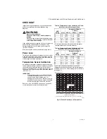
Temperature Sensor Calibration
As wire length increases, resistance increases and thus
the temperature reading increases. If necessary, calibrate
the sensor input by reducing the value by the amount
shown in the Tables 3 and 4. For example, a wire run with
18 gauge wire of 1,000 feet, requires a calibration offset of
-6.0°F (-21° C).
IMPORTANT
If the calibration value in the table exceeds the
controller’s calibration limits of +/-10° F (+/-6° C),
you must use a heavier gauge wire. For
example, with a wire run of 1,000 feet you must
use 20 AWG wire or heavier in order to calibrate
for wire loss within the limits of the controller.
Refer to “3.2.2.2. CALIBRATE (the sensor)” on page 20
for the instructions to enter the calibration value.
Table 3. Temperature Sensor Calibration for Resis-
tance Loss due to Wire Length (Feet).
a
This is the distance from the controller to the sensor
(already accounts for round trip distance).
Table 4. Temperature Sensor Calibration for Resis-
tance Loss due to Wire Length (Meters).
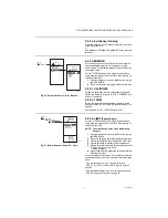
Fig. 19 shows how sensor resistance varies with
temperature for a sensor having a positive temperature
coefficient (PTC) of 2.1 Ohms per degree F (3.85 Ohms
per degree C).
Fig. 19. Sensor Resistance vs. Temperature.
AWG
Rating
m
Ω
/ft
Temperature Offset in
° F (Foot)
a
200 ft
500 ft
1,000 ft
14
2.5
0.46
1.14
2.28
16
4.0
0.72
1.82
3.64
18
6.4
1.16
2.90
5.82
20
10.2
1.86
4.64
9.28
22
16.1
2.92
7.32
14.64
AWG
Rating
m
Ω
/ft
Temperature Offset in
° C (Meter)
a
100 m
200 m
300 m
14
8.3
0.44
0.86
1.30
16
13.2
0.68
1.38
2.06
18
21.0
1.10
2.18
3.28
20
33.5
1.74
3.48
5.22
22
52.8
2.74
5.48
8.22
M24304
TEMPERATURE (DEGREES)
RESISTANCE (OHMS)
1403
1317
1231
1145
1059
973
20
40
60
80 100 120 140 160 180 200 220
0
10 20 30 40 50 60 70 80 90 100
°F
°C
0
-20
-40
120
110
250
-40
-20 -10
-30
1489
887
801
1097 ± 0.08 OHMS
AT 77°F (25°C)
POSITIVE TEMPERATURE COEFFICIENT (PTC) OF 2.1 OHMS PER °F
1
1