


Q179A,B GAS PILOT BURNER ASSEMBLIES
60-2032-05
4
a
Orifice 0.025 in. (0.635 mm) diameter.
b
Orifice 0.0130 in. (0.330 mm) diameter (order separately).
c
Orifice 0.028 in. (0.711 mm) diameter.
INSTALLATION
When Installing this Product…
1.
Read these instructions carefully. Failure to follow them
could damage the product or cause a hazardous
condition.
2.
Check the ratings given in the instructions and on the
product to make sure the product is suitable for your
application.
3.
Installer must be a trained, experienced, flame safeguard
control technician.
4.
After installation is complete, check out product opera-
tion as provided in these instructions.
Follow instructions provided by burner manufacturer if
available. If no instructions are furnished, use the following
recommendations.
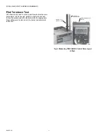
Mounting
The Q179 has two mounting ears at the burner and two
mounting holes in the bracket (see Fig. 2). If the mounting
holes in the bracket are used, it may be necessary to break off
one of the mounting ears so that the bracket fits flush with the
burner.All models are supplied with a factory-installed 1/4 inch
compression coupling inlet fitting. When a fitting is used,
remove the compression nut and install the new fitting.
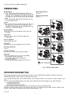
Gas Pressure Regulation
Use a pressure regulator in the line supplying the Q179 pilot.
Adjust the regulator for a maximum inlet gas pressure of eight
inches water column. The minimum inlet gas pressure must be
two inches water column to assure reliable lightoff of the main
flame.
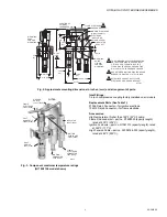
Install the Q179A,B
Install the pilot assembly so the pilot flame has full contact with
the gas stream from the main burner heads or jets. Mount the
flame electrode just inside the junction of the main and pilot
flame to prove both flames. Mount the pilot so that it fires in the
same direction as the draft at the mounting point, rather than
where the draft is at right angles to flame travel. Keep the pilot
burner below or behind the main burner so that the burner
frame and refractory will help protect the pilot from radiant
heat. Locating the pilot in the secondary air stream will also
provide considerable cooling. The primary air adjustment must
be accessible and outside the high temperature area.
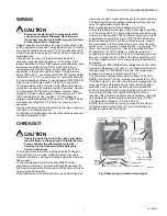
Do Not Install the Q179A,B—
—
Where ambient temperatures exceed those specified in
Fig. 3.
—
Where excessive draft turbulence can deflect the pilot
flame away from the main burner or flame electrode.
—
Where the ignition electrode is within arcing distance of
any metal other than the pilot burner head.
—
Where the flame electrode contacts any metal part of
the installation.
—
Where the flame electrode is closer than one inch from
a radiant refractory.
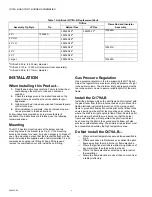
Table 1. Additional Q179A, B Replacement Parts
Assembly Tip Style
Tip
Orifice
Flame Rod and Insulator
Assembly
Natural Gas
LP Gas
I
395390-25
a
395390-13
b
133448A
45° I
105064A
395390-25
a
45° RH
395390-25
a
45° LH
395390-25
a
T
395390-28
c
133451A
45° Y
395390-28
c
45° T
395390-28
c
Large I
395390-25
a
133448A