Honeywell Q179A Product Data Download Page 2

Q179A,B GAS PILOT BURNER ASSEMBLIES

60-2032—05

2

ORDERING INFORMATION

When purchasing replacement and modernization products from your TRADELINE® wholesaler or distributor, refer to the 
TRADELINE® Catalog or price sheets for complete ordering number.

If you have additional questions, need further information, or would like to comment on our products or services, please write or 
phone:

1.

Your local Honeywell Automation and Control Products Sales Office (check white pages of your phone directory).

2.

Honeywell Customer Care
1885 Douglas Drive North
Minneapolis, Minnesota 55422-4386

In Canada—Honeywell Limited/Honeywell Limitée, 35 Dynamic Drive, Toronto, Ontario M1V 4Z9.
International Sales and Service Offices in all principal cities of the world. Manufacturing in Australia, Canada, Finland, France, 
Germany, Japan, Mexico, Netherlands, Spain, Taiwan, United Kingdom, U.S.A.

SPECIFICATIONS

Model Number:

Q179A—Gas pilot assembly with ignition and flame elec-

trodes. Use with intermittent or interrupted ignition. Ignition 
electrode is for use with 6,000V grounded secondary-igni-
tion transformer. (Q179A1183 has ignition electrode [spark] 
only.)

Q179B—Gas pilot assembly with flame electrode (rod) only. 

Use with continuous pilot.
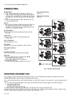
Burner:

Primary aerated. Stainless steel fins provide proper flame con-

tact area to ground area. Flame electrode and ground 
bracket are furnished with each tip. Available tips are illus-
trated in Fig. 1, and listed in Table 1.

Mounting Means:

Bracket has holes for side mounting and two lugs for end 

mounting.

Type of Gas:

Natural; for LP gas, order LP orifice separately (see

Accessories).

Gas Consumption:

Approximately two cu ft/hr.

Electrodes:

Stainless steel, maximum temperature 1750°F (954°C).

Electrode Insulator(s):

Ceramic.

Electrical Connector:

Rajah connector (both male and female supplied).

Approvals:

Underwriters Laboratories Inc. listed, File No. MP268;

Industrial Risk Insurers acceptable;
CSA certified, Master File No. LR-95329-1;

Factory Mutual approved;

American Gas Association certified, No. G140.401.

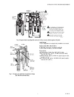
Mounting Dimensions: 

See Fig. 2.

Maximum Temperature:

See Fig. 3.

Fig. 1. Pilot tip assembly styles.

A

"I" PORT

B

45° "I" PORT

D

45° RIGHT HAND "ELL"

E

45° LEFT 

HAND "ELL"

H

45° "T" PORT

G

45° "Y" PORT

F

"T" PORT

M5007

1 NOTE THAT GROUND PRONG 

IS CUT OFF CLOSE TO BASE.

1

Summary of Contents for Q179A

Page 1: ...or applications requiring an interrupted or intermittent electrically ignited gas pilot burner Q179A1183 is an I port burner with an ignition electrode spark only Q179B has only the flame electrode and is suitable for use in continuous pilot applications Primary aerated type burner is equipped with stainless steel fins that provide the proper flame rod area to ground area ratio for maximum flame s...

Page 2: ...for use with 6 000V grounded secondary igni tion transformer Q179A1183 has ignition electrode spark only Q179B Gas pilot assembly with flame electrode rod only Use with continuous pilot Burner Primary aerated Stainless steel fins provide proper flame con tact area to ground area Flame electrode and ground bracket are furnished with each tip Available tips are illus trated in Fig 1 and listed in Ta...

Page 3: ...MOUNTING EARS FOR END MOUNTING 1 THIS DIMENSION WILL VARY DEPENDING ON THE FLAME ELECTRODE AND INLET FITTING USED FORMATION OF THE FLAME ELECTRODE AND GROUND FINS WILL VARY WITH THE BURNER TIP USED GAP BETWEEN IGNITION ELECTRODE AND BURNER TIP MUST BE 1 16 TO 3 32 INCH Q179A1183 DOES NOT HAVE FLAME ELECTRODE OR GROUND BRACKET 3 74 2 MOUNTING HOLES 7 32 DIA FOR SIDE MOUNTING INSULATOR BRACKET CLAMP...

Page 4: ...olumn The minimum inlet gas pressure must be two inches water column to assure reliable lightoff of the main flame Install the Q179A B Install the pilot assembly so the pilot flame has full contact with the gas stream from the main burner heads or jets Mount the flame electrode just inside the junction of the main and pilot flame to prove both flames Mount the pilot so that it fires in the same di...

Page 5: ... excess secondary air velocity or a severe draft condition causes the pilot flame to make intermittent contact with the flame electrode rod or grounding bracket The performance of the pilot assembly can be determined by measuring the flame signal developed with the pilot operating The flame signal current voltage measurement requires the use of an appropriate volt ohmmeter Most existing Honeywell ...

Page 6: ...e the main fuel valve s can be opened perform a pilot turndown test Follow the procedures in the Instructions for the appropriate Flame Safeguard Control and in the burner manufacturer s instruction Fig 5 Measuring 7800 SERIES Control flame signal voltage NEGATIVE METER LEAD POSITIVE METER LEAD ONE MEGOHM VOLT METER M7382 ...

Page 7: ...Q179A B GAS PILOT BURNER ASSEMBLIES 7 60 2032 05 ...

Page 8: ...neywell International Inc 1985 Douglas Drive North Golden Valley MN 55422 Honeywell Limited Honeywell Limitée 35 Dynamic Drive Toronto Ontario M1V 4Z9 customer honeywell com U S Registered Trademark 2011 Honeywell International Inc 60 2032 05 JPG Rev 03 11 Printed in U S A ...

Reviews: