background image

C7012A,C,E,F,G SOLID STATE PURPLE PEEPER® ULTRAVIOLET FLAME DETECTORS

15

60-2398-17

TROUBLESHOOTING

WARNING

Electrical Shock Hazard.

Can cause serious injury or death.

Be extremely careful while troubleshooting the 

detector; line voltage is present on some of the 

terminals when power is on.

Open the master switch to disconnect power before 

removing or installing the detector or its cover. More 

than one disconnect can be involved.

Equipment Required

1.

Use Honeywell W136A Volt-ohmmeter with a zero to 

25 microampere scale to check out most Honeywell 

flame safeguard controls.

2.

Use 196146 Meter Connector Plug provided with the 

W136A.

3.

To measure the flame signal of the BCS 7700 control, 

a volt-ohmmeter with a minimum sensitivity of 20,000 

ohms/volt and a zero to five Vdc or zero to ten Vdc scale 

is recommended. When the Keyboard Display Module is 

included with the control, the module displays a flame 

signal.

4.

For 7800 SERIES controls, a ohm/voltmeter with an 

input impedance of one megohm/volt and a zero to 

five or ten Vdc scale is suggested. When the Keyboard 

Display Module is included with the control, the module 

displays a flame signal.

5.

For replacement parts, see Specifications section.

UV Sensor Tube Test

See UV Sensor Tube Test in Adjustments and Checkout.

Unsatisfactory Flame Signal

If a satisfactory flame signal (see Table 1) cannot be obtained 

while adjusting the sighting position of the detector, follow 

these procedures. If you encounter other problems in the 

system, refer to the Troubleshooting section in the instructions 

for the appropriate flame safeguard control.

NOTE: For instructions for replacing the viewing window, 

sensing tube, and coil and shutter assembly, see 

the Service section.

Troubleshooting Procedures

First perform the Preliminary Inspection. Then follow the 

applicable procedures for either a low reading or a zero 

reading on the meter. After reinstalling the detector or replacing 

its cover, recheck the meter reading. To try to obtain the proper 

flame signal, adjust the position of the detector. 

If you complete all of the procedures and cannot yet obtain 

a proper flame signal, replace the detector.

Preliminary Inspection

1.

Check for the proper line voltage. Make sure the master 

switch is closed, connections are correct, and power 

supply is of the correct voltage and frequency.

2.

Check the detector wiring for defects:

a. Incorrect connections.

b. Wrong type or size of wire.

c. Deteriorated wire.

d. Open circuits.

e. Short circuits.

f. Leakage paths caused by moisture, soot, or dirt.

3.

With the burner running, check the temperature at the 

detector. If it exceeds 175°F (79°C):

a. Add additional insulation between the wall of the 

combustion chamber and the detector.

b. Add a shield or screen to reflect radiated heat away 

from the detector, or

c. Add cooling (refer to Sight Pipe Ventilation and 

Accessories sections).

Removing Detector from the Sight 
Pipe

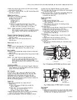
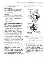
For C7012A,E or G (refer to Fig. 9); loosen the three screws 

holding the mounting flange; rotate the detector slightly so 

the screws clear the slots in the back section of the flange; 

separate the flange; and pull off the back section (with the 

UV sensor).

For C7012C or F (refer to Fig. 10); unscrew the collar from the 

pipe union and remove the detector.

NOTE: The detector is free when the collar is unscrewed; 

do not drop it.

Procedure for a Zero Meter Reading

1.

Replace the plug-in amplifier (if included). Then 

recheck the flame signal.

2.

Replace the ultraviolet sensing tube (see Service 

section). Then recheck the flame signal.

3.

For a C7012E or F, replace the coil and shutter assembly 

(see Service section). Then recheck the 

flame signal.

4.

If you still cannot obtain a meter reading, replace 

the detector.

IMPORTANT

At the completion of Troubleshooting, be sure to 

perform the Adjustments and Checkout procedures.

Summary of Contents for Purple Peeper C7012A

Page 1: ...n sensing tube and quartz viewing window are field replaceable Threaded conduit fitting and color coded leadwires allow rapid electrical installation Two flame detectors can be wired in parallel to reduce nuisance shutdowns in difficult flame sighting applications A swivel mount is available to facilitate flame sighting Models are available with a 40 F 40 C rating C7012A C G Designed for use with ...

Page 2: ...Ultraviolet Flame Detector For use in rectification type flame safeguard systems C7012C Solid State Purple Peeper Ultraviolet Flame Detector Same as C7012A except with explosion proof housing for use in hazardous locations C7012E Self Checking Solid State Purple Peeper Ultraviolet Flame Detector For use with R7247C and R7847C Dynamic Self Check Amplifiers C7012F Self Checking Solid State Purple Pe...

Page 3: ... System See form number 65 0312 for Certificate Agreement Approvals Underwriters Laboratories Inc Listed 120 Volt Models Only C7012A and E except C7012E1161 and E1278 File no MP268 C7012C and F For use in hazardous locations Class I Groups C and D Class II Groups E F and G File no E34649 Canadian Standards Association Certified 120 Volt Models Only C7012A and E Master File LR95329 1 Factory Mutual...

Page 4: ...or must respond only to the flame produced by the burner it is supervising 6 Do not connect more than two C7012 Flame Detectors in parallel Proper flame detector installation is the basis of a safe and reliable flame safeguard installation Refer also to the burner manufacturer instructions Carefully follow the instructions for the best possible flame detection application Basic Requirements The co...

Page 5: ... nearly parallel to the axis of the flame permitting the detector to view a large portion of the first 30 percent of the flame closest to the burner nozzle as illustrated in Fig 3 Low angle sighting permits the detector to view a greater depth of flame thus reducing the effects of instabilities in the flame pattern Also the environment near the burner nozzle is usually cleaner than at any other pa...

Page 6: ...med at the first 30 percent of Flame A where the ultraviolet radiation is most intense It sights the tip of Flame B but it is not aimed at the first 30 percent of Flame B where UV is intense Detector A is repositioned to assure maximum response to Flame A while rejecting Flame B Similarly Detector B is positioned to assure maximum response to Flame B while rejecting Flame A If you reposition a det...

Page 7: ...e Fig 5 8 The C7012A C G Flame Detectors do not have the oscillating shutter mechanism for checking the UV sensor so they can be mounted in any position suitable for the temperature environment The C7012E F Self Checking Flame Detectors incorporate an oscillating shutter mechanism and therefore require special consideration for mounting positions other than vertically sighting downward or upward T...

Page 8: ...itable for at least 167 F 75 C c For high temperature installations use Honeywell specification No 32004766 003 or equivalent for the F leadwire This wire is rated up to 400 F 250 C for continuous duty It it tested for operation up to 20 000 volts and for breakdown up to 32 000 volts For the other leadwires use moisture resistant no 14 wire selected for a temperature rating above the maxi mum oper...

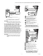
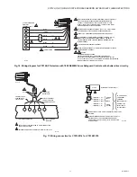
Page 9: ...NG LEADWIRES SUPPLIED WITH C7012E JUNCTION BOX CONDUIT CONTAINING F G LEADWIRES CONDUIT CONTAINING POWER AND SHUTTER LEADWIRES M20035 CONTROL CABINET C7012E 1 1 1 ISOLATE F G LEADWIRES FROM OTHER LINE VOLTAGE WIRING BY A MINIMUM OF 2 INCHES YELLOW GREEN YELLOW BLACK M9371 G C7012A C G 1 FLAME SAFEGUARD CONTROL TERMINAL STRIP OR WIRING SUBBASE 1 TWO C7012A C OR G DETECTORS CAN BE CONNECTED IN PARAL...

Page 10: ...MPERS BETWEEN TERMINALS 14 AND 13 AND BETWEEN TERMINALS 12 AND F IF THERE ARE JUMPERS AND INSTALL A JUMPER BETWEEN TERMINALS 13 AND 7 VOLTAGE AND FREQUENCY RATING OF THE C7012E OR F MUST MATCH THE POWER SUPPLY OF THE FLAME SAFEGUARD CONTROL IDENTIFICATION LABEL ON LEADWIRES 2 3 4 1 5 WHITE YELLOW GREEN M9375A C7012E OR F 3 1 AN R7247C DYNAMIC SELF CHECK AMPLIFIER MUST BE USED WITH AN R4140 BC7000 ...

Page 11: ...N LEADWIRES CHECK L1 CONNECTION OF 7800 SERIES DEVICE BEING INSTALLED TO LOCATE CORRECT TERMINAL CAUTION EQUIPMENT DAMAGE HAZARD SERIOUS DAMAGE TO SHUTTER MECHANISM CAN OCCUR ON EC78XX SERIES RELAY MODULE APPLICATIONS ONLY INSTALL A 220 240 VAC TO 120 VAC 10 VA MINIMUM STEP DOWN TRANSFORMER ORDER SEPARATLY TO DRIVE THE SHUTTER 2 3 4 5 6 7 5 7 1 2 BLUE BLACK BLACK YELLOW GREEN S L2 L2 L1 6 M6823B 1...

Page 12: ...ntrol amplifier see Fig 17 The W136A Meter then directly reads the flame signal in microamperes Refer to Table 1 for minimum acceptable flame currents Fig 18 Measuring microamp flame signal The R7747C and R7847C Amplifiers used with the BCS 7700 and 7800 Series Flame Safeguard controls respectively have a dc voltage flame signal output For the R7747C Amplifiers a volt ohmmeter with a 20 000 ohm vo...

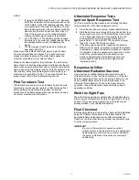
Page 13: ...ame safeguard control 1 Close the pilot and main burner manual shutoff valves 2 Start the burner and run through the Ignition period Igni tion spark should occur but the flame relay must not pull in The flame signal should not be greater than 0 25 microampere for most Honeywell controls and not greater than 1 0 Vdc for BCS 7700 controls nor larger than 0 25 Vdc for 7800 Series controls 3 If the fl...

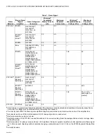
Page 14: ...g usually between 0 9 to 2 3 Vdc on the S7800 Keyboard Display Mod ule g Currently obsolete Table 1 Flame Signal Flame Detector Plug inFlame Signal Amplifier Flame Safeguard Control s Minimuma Acceptable Steady Current uA Maximum Expected Current uA Minimuma Acceptable Steady Voltage Vdc Maximum Expected Voltage Vdc C7012A C R7247A R4075C D Eg R4138C Dg R4140G L M BC7000L 2 0 6 0 R7247Bb Ampli Che...

Page 15: ...follow the applicable procedures for either a low reading or a zero reading on the meter After reinstalling the detector or replacing its cover recheck the meter reading To try to obtain the proper flame signal adjust the position of the detector If you complete all of the procedures and cannot yet obtain a proper flame signal replace the detector Preliminary Inspection 1 Check for the proper line...

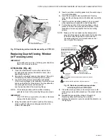
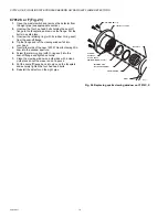
Page 16: ...the holes in the socket 8 Carefully push the new tube firmly into the socket On a C7012E or F the alignment guide snaps into place around the tip of the tube 9 Make sure the new UV sensor tube is seated securely NOTE The cover for a C7012C or F has a small hole that is keyed to a pin on the body flange Fig 8 10 Replace the detector cover Fig 21 Replacing ultraviolet radiation sensing tube Replacin...

Page 17: ...to the window aperture with either side toward the flame 7 Insert two rubber mounting gaskets only one gasket when replacing a focusing lens into the aperture 8 Put the back section of the mounting flange rubber washer and fiber neoprene gasket into place on the faceplate and securely tighten the three mounting screws NOTE Make sure the red rubber washer between the gray asbestos neoprene gasket a...

Page 18: ...ow fall into your hand 5 Insert either side of the new 122037 Quartz Viewing Win dow into the window aperture 6 Screw the retaining ring with O ring seal into the seal off flange and tighten securely 7 Clean the viewing window on both sides with a clean cloth placed over the eraser end of a pencil 8 Put the seal off flange back into place on the faceplate and securely tighten the four hex head bol...

Page 19: ...C7012A C E F G SOLID STATE PURPLE PEEPER ULTRAVIOLET FLAME DETECTORS 19 60 2398 17 ...

Page 20: ...roducts visit ThermalSolutions honeywell com or contact your Honeywell Sales Engineer Honeywell Process Solutions Honeywell Thermal Solutions HTS 2101 CityWest Blvd Houston TX 77042 ThermalSolutions honeywell com C7012A C E F G SOLID STATE PURPLE PEEPER ULTRAVIOLET FLAME DETECTORS U S Registered Trademark 2021 Honeywell International Inc 60 2398 17 Rev 05 21 Printed in United States ...

Reviews: