


150
RP-2002 Series Manual —
P/N 53039:E6 1/26/2017
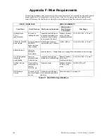
Appendix F: Wire Requirements
Connecting external system accessories to the main circuits must be carefully considered to ensure
proper operation. It is important to use the correct type of wire, gauge and run length for each
circuit. Reference the chart below to specify wire requirements and limitations for each circuit.
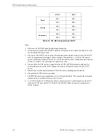
CIRCUIT CONNECTIONS
WIRE REQUIREMENTS
Circuit Type
Circuit Function
Wire Type and Limitations
Recommended
Max. Distance
Feet (meters)
Wire Gauge
Initiating Device
Circuit
(power-limited)
Connects to
Initiating Devices
Untwisted, unshielded wire
or twisted, unshielded wire
(maximum loop resistance
not to exceed 100 ohms)
Distance limitation
set by 100 ohm
resistance limitation
12-18 AWG (3.25 - 0.75 mm
2
)
ANN-BUS (EIA-485)
power-limited
Communication for
ANN-BUS
annunciator and
relay modules
Twisted pair a maximum
loop resistance of 120 ohms
6,000 (1,800 m)
12-18 AWG (3.25 - 0.75 mm
2
)
ANN-BUS Power
Power for
ANN-BUS
annunciators
Refer to Table 2.1, “Wiring Distances,” on page 36 for information on device wiring.
24 VDC Regulated,
resettable,
nonresettable
Power for
accessories and
twisted pair, unshielded wire
4-wire devices
Untwisted, unshielded
or
Distance limitation
set by 4 volt
maximum line drop
12-18 AWG (3.25 - 0.75 mm
2
)
Auxiliary Trouble
Input
Open Collector
trouble input for
CHG-75,
CHG-120, etc.
Single conductor
Distance limitation
20 feet in same
room
18 AWG (0.75 mm
2
)
NAC/Solenoid
Outputs
Connects to NAC
devices or Release
devices
Untwisted, unshielded pair
wire or twisted, unshielded
pair wire
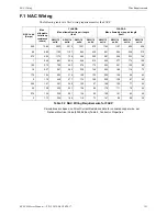
Refer to Section F.1 on page 151.
Table F.1 FACP Wire Specifications
Summary of Contents for NOTIFIER RP-2002C
Page 158: ...Cut along dotted line ...