


RP-2002 Series Manual —
P/N 53039:E6 1/26/2017
11
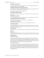
FACP Main Circuit Board
6
6
T
B
6
Z
O
N
E
6
S
W
1
T
B
4
/
T
B
6
1
/6
2
3
5
4
A
A
A
A
2
2
D
ummy load all unused circuits
with 4.7K
Ω
, ½
watt End-
of-Line
re
si
stor
s
S
tyle Z
(Class A
) NAC
S
tyle D
(C
la
ss
A
) IDC
CAC-
5X
Cl
ass A Co
nvert
er Modu
le
3 Prog
ramm
able R
elays
Non
sup
ervised
re
lay co
nta
cts
Co
nta
ct
Ra
ting
s
2.0
amp
s @ 3
0 V
DC (re
sistive
)
0.
5 amp
@ 3
0 V
AC (
res
is
tive
)
Co
nta
ct
s sh
own
be
lo
w in n
or
mal
con
di
tion
(A
C po
wer
with n
o a
lar
m,
trou
ble
, or
su
pe
rviso
ry
activity)
A
Fa
il S
afe
Trou
ble re
la
y
switche
s to
th
e NC p
osition
du
ring
tr
ou
ble
c
on
di
tio
ns
an
d
un
de
r lo
ss of al
l po
we
r.
(*Fa
cto
ry d
ef
aul
t r
ela
y p
rog
ra
mmi
ng
)
Al
ar
m*
Tr
oubl
e*
S
uper
vi
sor
y*
Cl
ass A
Conve
rte
r Modu
le
R
emove
jumpe
r JP43
to
di
sab
le Gr
ound
Fau
lt
D
ete
ction cir
cu
it
(only w
ith
ap
pr
ova
l of
AH
J)
Cu
t this
jum
pe
r to
sup
er
vise
the
4
X
TM
mo
du
le whe
n
insta
lle
d (se
e J4
& J5
)
Cu
t th
is jum
pe
r to
en
ab
le
S
upe
rv
iso
ry
Re
lay wh
en
4X
TM
mo
du
le
is
in
sta
lled
A
uxi
lia
ry
Tr
oubl
e Inp
ut
Kiss-
off LED
ANN-
SE
C
op
tion
car
d con
nec
tor
Batt
ery
24 VDC,
supe
rvised,
no
npower
-limit
ed
26
A
mp H
our maximum
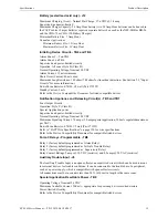
Basic Syste
m
Connectio
ns
Power Supply Connector
Fo
r mo
re s
pecifi
c UL wiring
inf
ormat
ion,
ref
er to
Im
portant!
Removing Gr
ound Faul
t Disable
Jumper J
P43 v
oids
UL/
N
FP
A
S
tyle/Class
in
dent
ificati
ons
fo
r circuit
s. Remove jump
er
JP4
3
on
ly
wit
h t
he appr
oval of t
he local AHJ
(A
ut
horit
y Ha
vin
g
Ju
risdicti
on).
Sp
ecial Ap
plicat
ion
DC
Power Ou
tp
uts
24 VDC)
Nonsupe
rvise
d,
po
wer-li
mited
circui
ts
Sup
ervise w
ith a powe
r sup
ervision rel
ay
EOL
R
-1
Resettab
le Power
- 24 VDC fi
lte
red,
power
-limit
ed,
C
lass 2 (0.
5 amp
maximum) t
o
smoke det
ect
ors
(IDC).
Sup
ervise w
ith po
w
er
sup
ervision
rela
y EO
LR-1.
N
on
res
et
ta
bl
e or
R
es
et
ta
bl
e Po
w
er
Jumper select
able
b
y JP31,
24 VDC
filte
red, p
ower-l
imited, Cla
ss
2 (
0.5 a
mp
maximum).
Supe
rvise
wit
h power
supvervision re
lay
EO
LR-1
. Nonre
se
ttabl
e
Power
suit
ab
le
for
po
wering
smoke
det
ecto
rs.
Conf
igur
e TB
9,
Termin
als 1
&
2
as
Reset
tab
le or Nonre
se
ttable
P
ower.
•
R
eset
tab
le Power
- jump
er JP
31 pins 2
& 3
•
N
on
reset
table
P
ower - jumpe
r JP3
1 pins
1 & 2 (as sh
own)
4 3
2 1
{
{
Ou
tp
ut Cir
cuit #
1
NA
C
Outp
ut Ci
rc
uit
#3
NA
C
Pu
sh
switch
d
own
to
up
gr
ad
e so
ftw
ar
e
IDCs
1 t
hroug
h 6,
St
yl
e B
(Cl
ass
B)
(S
uperv
ise
d,
Power
-L
imi
ted,
Cl
ass
2)
(S
ee St
yl
e D
ill
ust
rat
ed
near
ri
gh
t edge of boar
d.)
4.
7Kohm, ½
watt
E
nd-of
-Li
ne Resi
st
or PN
71252
In
it
iat
ing D
e
vi
ce Cir
cui
ts
rp2002layout.wmf
N
orm
ally
Open
Wat
erf
low
Devi
ces or
Press
ure
Swit
ches
Inpu
t IDC
Wa
te
rfl
ow
Cir
cui
t #6
O
u
tpu
t
Ci
rc
uits
- TB5 &
TB7
S
pe
cia
l Ap
pl
icatio
n P
ow
er
In
this
examp
le
NAC
Outp
ut
Cir
cu
its #
1, #
3,
&
#4,
St
yl
e Y
(C
la
ss B) (Su
pe
rv
ise
d,
P
ower
-Li
mit
ed
, C
las
s
2)
NAC
O
utp
ut
Circ
uit
#
2 (R
ele
as
ing
) is
S
ty
le
Y
(C
las
s
B)
(Sup
er
vi
sed
, N
onp
ow
er
-L
im
ited
, C
la
ss
1)
3
.0
am
p m
ax.
pe
r ci
rc
ui
t.
(S
ee
St
yle
Z
illus
tra
te
d ne
ar
ri
gh
t ed
ge
of
bo
ar
d.
)
4.7
K
ohm
, ½
w
att
En
d-
of-
Lin
e
Re
si
stor
P
N
712
52
Outp
ut
Ci
rc
ui
t #2
Re
le
asin
g
Inp
ut IDC
Ci
rc
ui
t #1
po
la
rized be
ll
po
la
rize
d
strob
e
po
la
riz
ed
ho
rn
smoke
de
tec
tor
pu
ll
st
ation
he
at
det
ecto
r
ma
nu
al
re
le
as
e
Normal
ly
Open Tamper
or
Pr
essur
e
Swi
tc
hes
Inp
ut I
D
C
Supe
rv
iso
ry
Circu
it #
5
Ou
tpu
t
Circu
it
#4
ab
or
t
switch
Summary of Contents for NOTIFIER RP-2002C
Page 158: ...Cut along dotted line ...