


RP-2001 Series Manual —
P/N 52985:D5 1/26/2017
33
ANN-BUS Devices
Installation
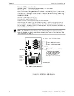
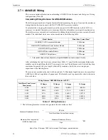
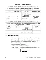
2.6.3 ANN-SEC Option Card
The ANN-SEC option card allows for a secondary ANN-BUS. Install the ANN-SEC as follows.
1.
Remove the chassis mounting screw to the right of TB3 and replace it with the supplied
0.5” x 4-40 male-female standoff.
2.
Install header J1 on the ANN-SEC into J13 on the main circuit board.
3.
Secure the ANN-SEC to the circuit board with the supplied screw.
2.7 ANN-BUS Devices
Guidelines
•
A variety of optional annunciation devices can be connected to an ANN-BUS communication
circuit. ANN Series devices can be connected to the primary communication circuit (EIA-485)
terminals on TB3. A secondary communication circuit (EIA-485) for these devices is available
at TB1 on the ANN-SEC card.
•
When using one ANN-BUS circuit, up to eight (8) annunciators can be supported.
•
When using both ANN-BUS communication circuits, the primary circuit supports up to three
(3) annunciators and the secondary circuit supports up to (5) annunciators.
Compatible devices include:
– N-ANN-80 LCD Annunciator
– N-ANN-80C LCD Indicator (Canadian Applications)
– N-ANN-S/PG Serial/Parallel Printer Interface Module
– N-ANN-I/O LED Driver Module
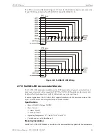
– N-ANN-LED Annunciator Module
– N-ANN-RLY Relay Module (can be mounted in the FACP chassis)
•
When operating two ANN-BUS circuits, only one N-ANN-S/PG Printer module can be used in
the system.
•
The panel is capable of operating a primary ANN-BUS (TB3) and a secondary ANN-BUS
(TB1 on ANN-SEC card) simultaneously.
TB1
J1
ANN-SEC
FACP Circuit Board
connector to J13 on
main circuit board
standoff and screw
Figure 2.15 Installing the ANN-SEC Option Card
an
n-
sec
200
1.w
m
f
!
WARNING: DISCONNECT ALL SOURCES OF POWER
DISCONNECT ALL SOURCES OF POWER (AC AND DC) BEFORE INSTALLING OR REMOVING
ANY MODULES OR WIRING.