
Configuration PC Preparation
NFN Gateway Configuration
31
NFN Gateway Installation & Operation Manual - P/N: 52306:Rev: D 06/01/07
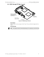
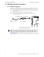
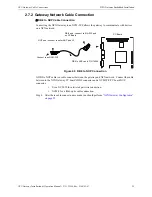
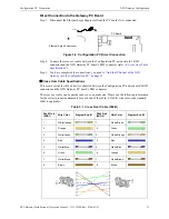
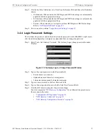
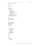
Direct Connection to the Gateway PC Board
Step 1. Disconnect the Ethernet Surge Suppressor from the PC board if it is connected.
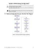
Figure 3.2 Configuration PC Direct Connection
Step 2. Connect the cross over cable between the Configuration PC network card’s RJ45
connector and the NFN Gateway PC board’s RJ45 connector (refer to
).
Step 3. You have completed the connections, you need to
Gateway into the Configuration PC” on page 32
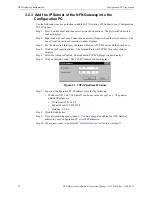
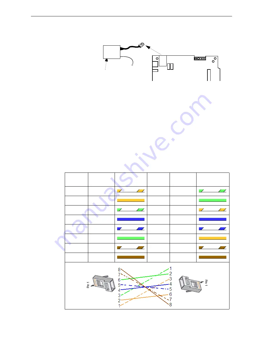
Cross Over Cable Specifications
This cross over cable will be directly connected between the Configuration PC network card’s RJ45
connector and the NFN Gateway PC board’s RJ45 connector.
The cross over cable can be purchased or you can make one. Please use the following information
for the correct pinout requirements for each end of the cable. EIA/TIA wire color-code standard
568B is applicable.
Ethernet Surge Suppressor
PC Board
Table 3.1 Cross Over Cable (568B)
RJ45 Pin #
(END 1)
Wire Color
Diagram End #1
RJ45 Pin #
(END 2)
Wire Color
Diagram End #2
1
White/Orange
1
White/Green
2
Orange
2
Green
3
White/Green
3
White/Orange
4
Blue
4
Blue
5
White/Blue
5
White/Blue
6
Green
6
Orange
7
White/Brown
7
White/Brown
8
Brown
8
Brown