


96
NFW-50X Manual —
P/N LS10129-001NF-E:C 7/25/2018
Programming
Master Programming Level
3.6.10 Clear Program
Pressing
2
while viewing Programming Screen #4, will select the Clear Program option. This will cause the
LCD to display the following screen:
Pressing
1
, for Whole System while viewing the Clear Program Screen, will clear all general system programming options and all pro-
grammed addressable devices from the nonvolatile memory of the FACP.
This function is useful when the control panel is first installed,
prior to autoprogramming. Note that it is necessary to autoprogram after using the Clear Whole System function.
Pressing
2
, for All Points while viewing the Clear Program Screen, will clear all programming related to the SLC loop and connected
addressable devices.
Before executing any of the Clear commands listed above, the control panel will provide a warning to the user by prompting with the fol-
lowing display:
Pressing
1
will cause the control panel to carry out the selected clear option. Pressing
2
will prevent programming from being cleared.
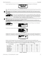
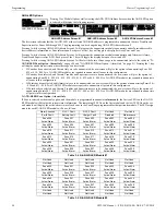
3.6.11 Program Check
The Program Check feature allows the programmer to view the zones which have been programmed to the
Notification Appliance Circuits on the control panel but have not been programmed to Initiating Devices as
well as other circuits with no input or output correlations. Pressing
3
while viewing Programming Screen
#4 will cause the following screen to be displayed:
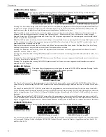
Pressing
1
while viewing the Program Check Screen will display an NAC screen similar to the following.
The example above indicates that NAC 1 has been programmed to Zones 005, 010, 012, 015, and 017 but no input devices have been
programmed to any of these zones. Use the up and down arrow keys to view all the NAC zones without input assignments for NAC 1
and NAC 2.
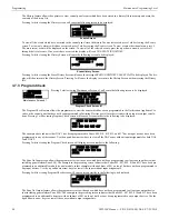
Pressing
2
while viewing the Program Check Screen #1 will display a screen similar to the following:
The Zone No Input screen allows the programmer to view the zones which have not been programmed to at least one input device (not
including general alarm Zone 00). The example in the preceding screen indicates that Zones 005, 007, 009, 010 and 011 have been pro-
grammed to an addressable module (control module in this example) with an address of 001 on loop 1 but have not been programmed to
any input devices. Use the up and down arrow keys to view all the zones without input assignments.
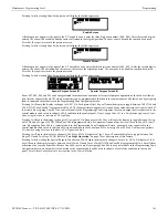
Pressing
3
while viewing Program Check Screen #1 will cause a screen similar to the following to be dis-
played:
The Zone No Output feature allows the programmer to view the zones which have not been programmed to at least one output device
(not including general alarm Zone 00). The example in the preceding screen indicates that Zones 05, 07, 09, 10 and 11 have been pro-
grammed to an addressable detector with an address of 001 on loop 1 but have not been programmed to any output devices. Use the up
and down arrow keys to view all the zones without output assignments.
PROGRAMMING
1=PASSWORD CHANGE
2=CLEAR PROGRAM
3=PROGRAM CHECK
Programming Screen #4
CLEAR PROGRAM
1=WHOLE SYSTEM
2=ALL POINTS
Clear Program Screen
WARNING!
SYSTEM CHANGE!
PROCEED?
1=YES 2=NO
PROGRAMMING
1=PASSWORD CHANGE
2=CLEAR PROGRAM
3=PROGRAM CHECK
Programming Screen #4
PROGRAM CHECK
1=NACS NO INPUT
2=ZONES NO INPUT
3=ZONES NO OUTPUT
Program Check Screen
NACS NO INPUT
NAC 1
005 010 012 015 017
ZONES NO INPUT
005 007 009 010 011
1M001
PROGRAM CHECK
1=NACS NO INPUT
2=ZONES NO INPUT
3=ZONES NO OUTPUT
Program Check Screen #1
ZONES NO OUTPUT
005 007 009 010 011
1D001