


NFW-50X Manual —
P/N LS10129-001NF-E:C 7/25/2018
31
Optional Module Installation
Installation
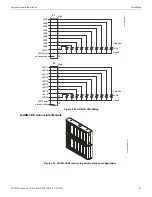
2.8.3 ANN-BUS Annunciators/Modules
ANN-BUS Wiring
This section contains information on calculating ANN-BUS wire distances and the types of wiring configurations (Class B).
Calculating Wiring Distance for ANN-BUS Modules
The following instructions will guide the installer in determining the type of wire and the maximum wiring distance that can be used
with FACP ANN-BUS accessory modules.
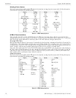
To calculate the wire gauge that must be used to connect ANN-BUS modules to the FACP, it is necessary to calculate the total worst case
current draw for all modules on a single 4-conductor bus. The total worst case current draw is calculated by adding the individual worst
case currents for each module. The individual worst case values are shown in the following table:
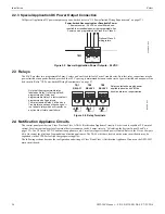
RTN-
OUT-
RTN+
OUT+
C
NO
NC
C
NO
NC
C
NC
NO
SUPV
TRBL
ALRM
ES
2
0
0
-PC
A
R
E
V
ES
5
0
-PC
A
R
EV
RMT SYNC
NAC1
1
2
3
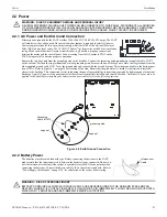
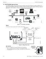
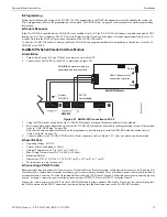
Figure 2.16 4XTM Connectors to NFW-50X Connectors
J12 & J13 Connectors
Standoff
Standoff
4XTM
FACP main circuit board
e
s
2
0
0
4
x
tm
f.
w
m
f
Jumper JS3
NOTE:
When a 4XTM is installed, enable supervision in panel programming.
Jumper JS3 on the FACP main circuit board can be used to configure the FACP supervisory relay for operation with the 4XTM module.
Relay 3 at TB3 must be programmed as a supervisory relay.
Jumpering pins 2&3 on JS3 will allow the 4XTM to generate a trouble if the supervisory contact opens.
Jumpering pins 1&2 on JS3 in will prevent generation of a trouble if the supervisory contact opens.
Model Number
Worst Case Current Draw
1
1 When powering the ANN-BUS from one of the (nonresettable) DC power outputs at TB11, the total
worst case current draw cannot exceed 1.0 amp. If sharing this DC output with other devices, the
worst case current drawn by these devices must be combined with the ANN-BUS current draw,
and the total cannot exceed 1.0 amp. If the total current demand exceeds 1.0 amp, refer to
“Powering ANN-BUS Devices from an Auxiliary Power Supply” on page 33.
N-ANN-80 LCD Annunciator
0.040 amps
N-ANN-100 LCD Annunciator
0.025 amps
N-ANN-S/PG Serial/Parallel Printer Interface Module
0.040 amps
N-ANN-I/O LED Driver Module
0.200 amps
N-ANN-(R)LED Annunciator Module
0.068 amps
N-ANN-RLY Relay Module
0.075 amps