background image

IDR-M Mimic Installation & Commissioning Manual

Installation Guide

5

997-412-000-3, Issue 3

June 2005

d. DO NOT locate the IDR-M mimic where it

is exposed to high levels of moisture.

e. DO NOT locate the IDR-M mimic where

there are high levels of vibration or shock.

f. DO NOT site the IDR-M mimic where there

would be restricted access to the internal
equipment and cabling/wiring connections.

2.2

Transient Protection

This equipment contains transient-protection
devices. Although no system is completely
immune from lightning transients and
interference, for these devices to function
correctly, and to reduce susceptibility, this
equipment 

must

 be earthed correctly.

As with all solid state devices, this system may
operate erratically or can be damaged if
subjected to lightning-induced transients.

The use of overhead or outside aerial wiring is
not recommended due to the increased
susceptibility to nearby lightning strikes.

Summary of Contents for NOTIFIER IDR-M

Page 1: ...IDR M mimic installation and commissioning manual 997 412 000 3 Issue 3 June 2005 ...

Page 2: ...IDR M Mimic Installation Commissioning Manual Contents i 997 412 000 3 Issue 3 June 2005 Quick Contents Reference by Section ...

Page 3: ...3 Installation 6 2 3 1 Checking Your Equipment for Damage 6 2 3 2 What To Do if Your Equipment is Damaged or Suspect 7 2 4 Mimic Display Components 8 2 4 1 Typical Configuration LEDs and I O 9 2 4 2 Typical Configuration Relays 10 2 5 Installation Procedure 11 2 5 1 IDR M Control Board Kit 11 2 5 2 IDR MD Mimic Driver Kit 14 2 5 3 LED Selection 16 2 5 4 Relay Selection 16 3 Commissioning 17 3 1 Pr...

Page 4: ...n and commissioning phases Important Note This manual must be read and its content clearly understood before proceeding with any work relating to the IDR M mimic Damage to the mimic display and or the fire control panel s may result from NOT following the recommended procedures described in this manual If there are any areas of doubt consult your supplier before continuing with the system installa...

Page 5: ...ly b 8 I O lines These can be configured to drive additional relays or to read switches first board only depending upon the configuration method used during commissioning see below Installation The IDR M mimic is easy to install providing the recommended procedures described in this manual are followed To avoid inadvertent contamination of the mimic PCB assemblies the manufacturer recommends they ...

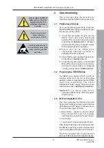
Page 6: ... see example to the left of this paragraph You are alerted to any areas where there may be a risk of damage to static sensitive devices if the recommended procedures described in this manual are not followed An example of an anti static caution is provided to the left of this paragraph 1 6 Tips Handy tips are included where appropriate to assist you in following quick and safe procedures for syste...

Page 7: ...re installing the IDR M mimic you must first ensure that the following criteria have been met Failure to do this may not only result in damage to the equipment but may also cause problems when commissioning the equipment or adversely affect its performance 2 1 1 Some DO s and DON T s Before selecting a location for the IDR M mimic DO make sure that a The operating ambient temperature is in the rec...

Page 8: ...d cabling wiring connections 2 2 Transient Protection This equipment contains transient protection devices Although no system is completely immune from lightning transients and interference for these devices to function correctly and to reduce susceptibility this equipment must be earthed correctly As with all solid state devices this system may operate erratically or can be damaged if subjected t...

Page 9: ... from its packaging and before you proceed with the installation check for any damage that may have been caused while in transit Note In the unlikely event that the any of the components of the IDR M mimic have been damaged you MUST NOT install it but return it to your supplier The procedure for returning faulty items is described in Section 2 3 2 What to do if Your Equipment is Damaged or Suspect...

Page 10: ...continue with the installation but contact your supplier for advice on what to do next Similarly if the product is found to be faulty during installation contact your supplier immediately 2 To aid your supplier and the manufacturer you are requested to note all the details relevant to your complaint date of receipt packaging condition etc and forward this to your supplier 3 Where the product needs...

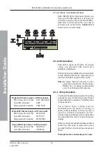
Page 11: ...be driven by one Control board Connection between each daisy chained Mimic Driver board andbetweentheControlboardandthe first Mimic Driver is via a Serial to Parallel Interface SPI bus refer to drawing on next page A 10 way ribbon cable is supplied for the interconnection of i The first Mimic Driver board and the Control board or ii The Mimic Driver board and the previous daisy chained Mimic Drive...

Page 12: ...e 9 997 412 000 3 Issue 3 June 2005 2 4 1 Typical Configuration LEDs and I O A typical interconnection of IDR M boards together with connections for LEDs and identification of the I O connectors is given below Jumper links must be set as described in Section 2 5 2 ...

Page 13: ...hod of interconnecting IDR MD Driver boards via the SPI bus and identification of the channels on the Mimic Termination boards is identical to that given in Section 2 4 1 and is not repeated here For simplicity only one Driver board and one Mimic Termination board is shown in each example Jumper links must be set as described in Section 2 5 2 Relays can also be connected to the I O lines on the Mi...

Page 14: ...tion in the network where station is a fire control panel repeater or mimic e RS485 serial data link A and B to the next station in the network f RS232 ribbon cable used in place of d and e above when IDR M is connected to ID2 net via a Network Gateway Unit NGU Connection to the NGU is made via two Isolated RS232 Boards see below left The ribbon cable is supplied with the Isolated RS232 Board The ...

Page 15: ...Ensure that the IDR Mimic does not share an address with a repeater and that the address matches that configured in the fire control panel Address Switch settings 1 on 1 2 3 4 5 6 1 1 0 0 0 0 0 2 0 1 0 0 0 0 3 1 1 0 0 0 0 4 0 0 1 0 0 0 5 1 0 1 0 0 0 6 0 1 1 0 0 0 7 1 1 1 0 0 0 8 0 0 0 1 0 0 9 1 0 0 1 0 0 10 0 1 0 1 0 0 11 1 1 0 1 0 0 12 0 0 1 1 0 0 13 1 0 1 1 0 0 14 0 1 1 1 0 0 15 1 1 1 1 0 0 16 0...

Page 16: ...e of connection used by the mimic in this case 1 for ID2 net via an RS232 link c Set switch 8 according to the type of network used by the fire panel in this case 1 for an ID2 net network Address Switch settings 1 on 1 2 3 4 5 6 1 1 0 0 0 0 0 2 0 1 0 0 0 0 3 1 1 0 0 0 0 4 0 0 1 0 0 0 5 1 0 1 0 0 0 6 0 1 1 0 0 0 7 1 1 1 0 0 0 8 0 0 0 1 0 0 9 1 0 0 1 0 0 10 0 1 0 1 0 0 11 1 1 0 1 0 0 12 0 0 1 1 0 0 ...

Page 17: ...ngs are overridden The DIP switch S1 allows the output channels to be configured as only FIRE indications or as FIRE and FAULT indications using alternate output channels S1 4 is used to select the required output channel indication S1 5 to S1 8 are used to set the zonal output channel indications if the first zone is not Zone 1 it can be set to a numerically higher zone in fixed increments of 64 ...

Page 18: ...D is connected to an output for which the link is fitted the LED will have a short life expectancy Conversely if a relay is connected to an output for which the link is notfitted therelaywillnotoperate Digital I O Inputs The IDR M Mimic Driver board is provided with eight pre configured digital inputs as defined below this is only applicable to an IDR M Mimic Driver board when used singularly or i...

Page 19: ...5 4 Relay Selection The Mimic Driver Board is capable of handling a maximum current of 80mA per relay Relays should therefore be chosen such that this value is not exceeded The minimum pull in voltage must be obtainable when the system is running on battery backup battery at 21V and with a maximum ambient temperature of 45o C Choose relays accordingly This consideration may also affect the choice ...

Page 20: ... mimic obtains 18 32V and 0V dc supplies either from the fire control panel auxiliary outputs or depending upon the IDR M mimic drive requirements from a local independent power supply Connections are made as described in Sections 2 4 and 2 5 1 Caution Do not remove power from a networked IDR M mimic while the system is still working 3 3 IDR Configuration Tool This Tool configures the IDR M mimic ...

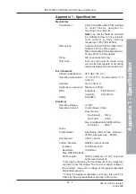
Page 21: ...rating temperature 5 C to 45 C recommended 5 C to 35 C Humidity 5 to 95 R H Height above sea level Maximum 2000m EMC Emissions EN 61000 6 3 Immunity EN 50130 4 Safety EN 60950 Electrical Operating Voltage 18 32V Operating Current Control Board 90mA Driver Board Each Board 10mA Each LED 4 4mA Max total Board 64 LEDs 265mA Each relay 80mA Fuses Control Board Resettable thermal fuse Nominal 250mA abs...

Page 22: ...C s D E L 4 8 3 r e v i r D 6 B C P l o r t n o C s D E L 8 4 4 r e v i r D 7 B C P l o r t n o C s D E L 2 1 5 r e v i r D 8 B C P l o r t n o C A 5 8 0 0 A 5 9 0 0 A 5 0 1 0 A 5 1 1 0 A 5 2 1 0 A 5 3 1 0 A 5 4 1 0 A 5 5 1 0 A 5 6 1 0 m u m i x a M m r a l A p u t e S n i m V 8 1 d e t s o o b n o N n i m V 4 2 d e t s o o B B C P l o r t n o C s D E L 4 6 r e v i r D I B C P l o r t n o C s D E ...

Page 23: ...e panel s battery calculations together with the relay currents Afully loaded non boosted panel PSU will require the following battery capacity to support the Mimic Driver C T x Iq Ia x 1 25 where C is the calculated battery capacity inAmpere Hours T is the required battery backup time in Hours lq is the IDR M mimic quiescent current inAmperes la is the IDR M mimic alarm current in Amperes 1 25 is...

Page 24: ...ystems co uk local distributor Every care has been taken in the preparation of this document but no liability can be accepted for the use of the information therein Design features may be changed or amended without prior notice Quality Systems Certificate No 154 Assessed to ISO9001 L O S S P R E V E N T ION CERTIFI C A T I O N B O A R D 007 ...

Reviews: