IDR-M Mimic Installation & Commissioning Manual
Installation Guide
16
997-412-000-3, Issue 3
June 2005
2.5.2.2 Mimic Termination Board
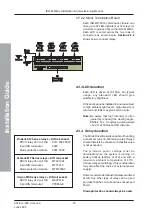
Each IDR-MD Mimic Termination Board can
drive up to 32 LED indicators or 32 relays (or
a mixture in groups of 8) on the IDR-M Mimic.
Each LED is wired across the two rows of
connectors as shown below.
shows how to connect relays.
2.5.3 LED Selection
Each LED is driven at 10-15mA. For typical
usage, any standard LED should give
satisfactory brightness.
If the mimic panel is installed in an area subject
to high ambient light levels, high-intensity or
low-current LEDs may give better results.
Note:
Be aware that high intensity is often
gained by reducing the viewing angle.
EN54-2: 12.7.1 requires a viewing angle
of 22.5° at 500lux and 3m distance.
2.5.4 Relay Selection
The Mimic Driver Board is capable of handling
a maximum current of 80mA per relay. Relays
should therefore be chosen such that this value
is not exceeded.
The minimum pull-in voltage must be
obtainable when the system is running on
battery backup (battery at 21V) and with a
maximum ambient temperature of 45
o
C.
Choose relays accordingly. (This consideration
may also affect the choice of external power
supply).
Some recommended industrial relays are listed
at left. Any other type of relay can be used
provided that the coil current does not exceed
80mA.
Diode protection should always be used.
Finder 60.12 Series DIN rail socket
DPCO relay 24V coil 10A
6012.9024.0040
8 pin DIN rail socket
9020
Diode protection module
9901-3000
Schrack MT Series DIN rail socket
DPCO relay 24V coil 10A
MT221024
8 pin DIN rail socket
MT78745
Diode protection module
MTMT00A0
Omron MK Series DIN rail socket
DPCO relay 24V coil 10A
MK2PN-S
8 pin DIN rail socket
PF083A-E


