68
Notifier FirstCommand Series Manual —
P/N LS10001-001NF-E:H 1/8/2018
Programming
Programmed Activation by FACP
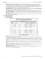
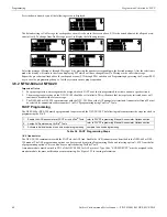
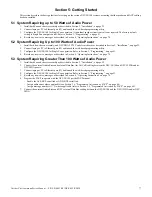
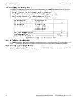
Press the down arrow key until the following screen is displayed.
The default setting is
No Message
for each speaker circuit. As shown in the screen above, Z32 is the zone dedicated for all speaker cir-
cuits (all call). To change from No Message, press
3
to display the following screens:
Select the message (Message 1 through Message 14) by pressing the number corresponding to the desired message. After the selection is
made, the display will return to the screen displaying Z32 which will have changed from No Message to the selected message.
Repeat the procedure outlined above for each speaker zone (Z32 through Z56) and then exit Programming by pressing the Escape (ESC)
key to save the programming changes. Test the system to ensure proper operation.
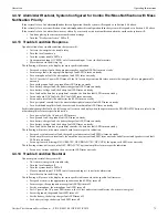
3.6.2 NFS2-640 and NFS-320
Important Notes:
1.
For proper operation, a message must be assigned to each FACP zone that is programmed to activate an audio speaker circuit.
2.
The message repeat setting on the NFC-50/100 should be set to infinite. This will ensure that lower priority activated zones will
continue to broadcast the voice message.
3.
The NFS2-640 or NFS-320 communicates with the NFC-50/100 over the ACS annunciator terminals. Annunciator Group M must
be selected for annunciator address number 1 in FACP programming using VeriFire
®
Tools.
FACP Programming
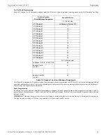
The NFS2-640 or NFS-320 must be programmed to operate with the NFC-50/100. The following table summarizes the steps involved in
programming the FACP.
ACS Annunciator
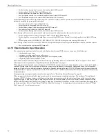
The NFC-50/100 communicates with the FACP via the ACS link. Enable the ACS Annunciator as described in the NFS2-640 or NFS-
320 manual. The ACS programming options can be accessed by entering Programming Mode and selecting option
7=SYS
from the list
of programming options. This can also be accomplished using VeriFire Tools.
A monitor module must be wired to TB1 of the NFC-50/100 for ACS protocol. Type Code, “ECS/MN SUPT” must be assigned to the
monitor module for mass notification event monitoring. See Figure 2.22 for wiring information.
ZONE MESSAGE
1=Z30 NO MESSAGE
2=Z31 NO MESSAGE
3=Z32 NO MESSAGE
ZONE MESSAGE
1=NO MESSAGE
2=MESSAGE 1
3=MESSAGE 2
ZONE MESSAGE
1=MESSAGE 3
2=MESSAGE 4
3=MESSAGE 5
ZONE MESSAGE
1=MESSAGE 6
2=MESSAGE 7
3=MESSAGE 8
ZONE MESSAGE
1=MESSAGE 9
2=MESSAGE 10
3=MESSAGE 11
ZONE MESSAGE
1=MESSAGE 12
2=MESSAGE 13
3=MESSAGE 14
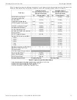
1.
Enable the ACS annunciator at FACP or in VeriFire
®
Tools
refer to FACP Programming Manual, Annunciator Options section
2.
Assign ACS points using VeriFire
®
Tools
refer to FACP Programming Manual, Annunciator Options section
3.
Activate individual devices to ensure proper programming
compare to desired programming
Table 3.4 FACP Programming Steps
Summary of Contents for Notifier FirstCommand Series
Page 84: ...84 Notifier FirstCommand Series Manual P N LS10001 001NF E H 1 8 2018 Notes ...
Page 86: ...Cut along dotted line ...
Page 88: ...Cut along dotted line ...
Page 92: ...92 Notes ...
Page 94: ...Cut along dotted line ...
Page 96: ...NOTIFIER 12 Clintonville Road Northford CT 06472 1610 USA 203 484 7161 www notifier com ...

