


60
Notifier SLC Wiring Manual —
P/N 51253:U5 12/20/2017
Power Considerations
Supervising 24 VDC Power
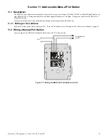
A.2.3 Using the Addressable Control Module Without Relay
An alternate method of supervising 24 VDC power fed to the Notification Appliance Circuit of the FCM-1 module eliminates the need
for a power supervision relay. This method uses a Notification Appliance Circuit from the control panel or power supply to supply power
to the FCM-1 modules. The control panel supervises this circuit, which can be either a Style Y or Style Z.
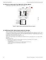
Style Y NAC Power Wiring
Program the NAC from the control panel for general alarm. (Refer to the programming manual or programming section of the FACP
documentation for instructions.) Note that if the NAC is a coded output, the FCM-1 output will be coded as well.
Refer to the
Device Compatibility Document
for compatible notification appliances.
•
The circuit is supervised and power-limited.
•
In this circuit, an external ELR
is
required at end of the NAC circuit.
•
Refer to the respective control panel installation manual for NAC terminal block connection information and ELR
value.
•
Remove internal resistor on each FCM-1 (see instructions in Figure 7.2 on page 40).
Connect the NAC power as follows:
Style Z NAC Power Wiring (Alternate)
Program the NAC from the control panel for general alarm. (Refer to the programming manual or programming section of the FACP
documentation for instructions.) Note that if the NAC is a coded output, the FCM-1 output will be coded as well.
Refer to the
Device Compatibility Document
for compatible notification appliances.
•
The circuit is supervised and power-limited.
•
In this circuit, an external ELR is
not
required at end of the NAC circuit.
•
Refer to the respective control panel installation manual for NAC terminal block connection information.
•
Remove internal jumper on each FCM-1 (see instructions in Figure 7.2 on page 40).
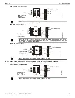
FCM-1
Note:
Drawing shows power
wiring only; SLC Wiring not
shown.
S
L
C
-n
ac
Y
1
tp
H
.w
m
f
NAC Terminal Block (24 VDC)
FCM-1
Circuit supervised
by control panel
Figure A.3 NFPA Style Y NAC Power (Alternate)