


Notifier SLC Wiring Manual —
P/N 51253:U5 12/20/2017
45
Section 9: Multiple Input/Output Modules
9.1 Description
9.1.1 FDM-1
The FDM-1 is similar to the FMM-1, except intended for use in intelligent two-wire systems providing two independent Style B (Class
B) IDCs at two separate, consecutive addresses. Addresses can start using either an even or odd number.
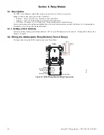
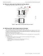
9.1.2 FDRM-1
The FDRM-1 is an addressable module that functions as two individual relay control modules (two isolated sets of Form-C relay con-
tacts) and two Class B monitor modules.
Ratings for the dry relay contacts on a Form-C module are:
For more information on the module specifications refer to the installation instructions provided with this device.
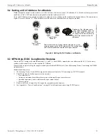
9.2 Setting the SLC Address
Each multiple input/output module is factory preset with an address of “00”. To set an SLC address, use a screwdriver to adjust the rotary
switches on the module to the desired address.
9.2.1 FDM-1
Each FDM-1 module can use up to two (2) addresses. The base address selected via the rotary address switches will be assigned to the
first monitored input. The next consecutive address will be assigned to the second monitored input.
9.2.2 FDRM-1
Each FDRM-1 module can use up to four (4) addresses. The base address selected via the rotary address switches will be assigned to
relay output #1 from 00 to 156. The module will automatically assign the next three addresses as appropriate to monitored input #1, relay
output #2, and monitored input #2.
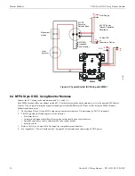
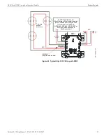
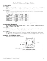
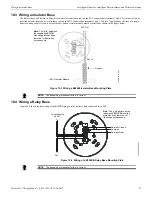
9.3 Wiring the Dual Monitor Module
The figure below shows the FDM-1 wired to the control panel.
Load Description
Application
Maximum
Voltage
Current
Rating
Inductive (PF = 0.35)
Non-Coded
25 VAC
2.0 A
Resistive
Non-Coded
30 VDC
3.0 A
Resistive
Coded
30 VDC
2.0 A
Inductive (L/R = 20ms)
Non-Coded
30 VDC
0.46 A
Inductive (PF = 0.35)
Non-Coded
70.7 VAC
0.7 A
Resistive
Non-Coded
125 VDC
0.9 A
Inductive (PF = 0.75)
Non-Coded
125 VAC
0.5 A
Inductive (PF = 0.35)
Non-Coded
125 VAC
0.3 A
Table 9.1
FMMtpH.wmf
SLC–
SLC+
9 H–
8 H+
7L+
6L–
A1
{
Base Address
{
Rotary
Switches
Areas used to record the device
address and SLC number.
Figure 9.1 FDM-1 Dual Monitor Module