


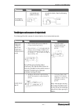


Configuring the Dip switch settings
The following table lists the different types of switches in ML200R.
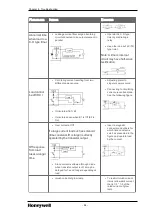
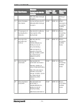
Table 24: ML200R Dip switch settings
Switches
Description
BOOT/NORMAL
switch
Downloads new operating system or upgrades CPU firmware
before releasing the product.
l
ON (right): For normal CPU operation mode.
l
OFF (left): Downloads new operating system. It is reserved
for use by Honeywell factory/authorized personnel.
Switching to this position by user is strictly prohibited.
Note: Both Boot/Nor switches must always be set to ON (right)
position. Setting it to OFF (left) position may cause abnormal
operation or damage to modules.
A/B side switch
(CPU position
designation switch)
Defines CPU classification
l
CPU module is ‘A’, if the switch is set to the left.
l
CPU module is ‘B’, if the switch is set to the right.
l
Two CPU must have different settings (you can check it
using software).
l
A same setting does not affect operation but may not
operate in a normal way.
Reset/D. Clear
switch
Resets CPU when switch is set to the left.
l
Left
→
Center: RESET
l
Left
→
more than 3s
→
Center: Overall RESET
Clears data when switch is set to the right.
l
Right
→
Center: clears memory area for M, auto-allocated
retain, general data memory address.
l
Right
→
more than 3s
→
Center: Clears memory area for
M, auto allocated retain, General Data Memory Address
and R Area.
Note: Data clear is only performed in ‘STOP’ mode.
3.4
Turn on and start up
Depending on the CPU types used, verify the following before turning on and starting the system.
- 42 -
Chapter 3 - Plan and Install MLPLC


