


PFU 780 · Edition 02.12l
62
Technical data
9 Technical data
Mains voltage:
220/240 V AC, -15/+10%, 50/60 Hz or
110/120 V AC, -15/+10%, 50/60 Hz,
for grounded and ungrounded mains.
Power consumption: < 8 VA.
Control inputs:
Input voltage/current:
Pilot burner, main burner, air valve, multi-flame control
and remote reset:
24 V DC, ± 10%, < 7 mA per input.
Input voltage for safety interlocks, digital input DI and
purge = mains voltage.
Input voltage of signal inputs:
Rated value
110/120 V AC
220/240 V AC
Signal “1”
80 – 132 V
160 – 264 V
Signal “0”
0 – 20 V
0 – 40 V
Frequenz
50/60 Hz
50/60 Hz
Rated value
24 V DC
Signal “1”
24 V, ±10%
Signal “0”
< 1 V
Inherent current:
Signal “1”
typ. 5 mA
Output voltage for voltage-related outputs = mains
voltage.
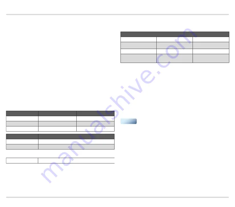
Contact rating
Gas valve V1, V2
Max. 1 A resistive
Max. 1 A cos
φ
0.3
Air valve
Max. 1 A resistive
Max. 1 A cos
φ
0.3
Ignition
Max. 1 A resistive
Max. 1 A cos
φ
0.3
Number of operating
cycles
Max. 1,000,000,
typically 400,000
Max. 250,000,
typically 100,000
Output current: max. 2 A per output, but total current
for valves and ignition transformer max. 2.5 A.
Operation and fault signalling contacts:
dry contact (floating), max. 1 A, 24 V, not fused inter-
nally.
Number of operating cycles:
Mains switch: 1000,
Reset/Information button: 1000.
▼