background image

www.honeywell.com/security

132  |  Performance Series HQA Digital Video Recorder User Guide

Viewing Network Information

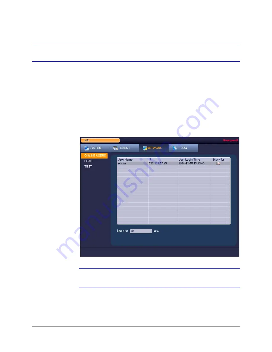
In the network information interface you can view and/or block online users, view network data 
transmission details, and perform network tests.

Viewing Online Users

You can view the user name, IP address, and login time of all online users. You can also block 
an online user for a specified period of time.

To view online users

Go  to 

Main Menu > Info > Network > Online Users

.

Note

Every five seconds, the DVR system detects newly added or dropped users, and 
updates the list of online users.

Summary of Contents for HRHH1081

Page 1: ...Document 800 19403 Rev A 12 2014 User Guide Performance Series HQA Digital Video Recorder DVR Models HRHM1041 X HRHH1161 X HRHH2042 X HRHH1081 X HRHH1163 X HRHH2082 X HRHH1083 X HRHH1166 X HRHH2086 X ...

Page 2: ...Issue Date Revisions A 12 2014 New document ...

Page 3: ... local codes and to maintain your warranty Regulatory Statements FCC Compliance Statement Information to the User This equipment has been tested and found to comply with the limits for a Class B digital device pursuant to part 15 of the FCC Rules These limits are designed to provide reasonable protection against harmful interference in a residential installation This equipment generates uses and c...

Page 4: ...erate the equipment This Class B digital apparatus complies with Canadian ICES 003 Cet appareil numérique de la Classe B est conforme à la norme NMB 003 du Canada Manufacturer s Declaration of Conformance North America The equipment supplied with this guide conforms to UL 60950 1 and CSA C22 2 No 60950 1 Europe The manufacturer declares that the equipment supplied is compliant with the essential p...

Page 5: ...d to your facility consult your product dealer or local power company 4 HEAT Situate away from items that produce heat or are heat sources such as radiators heat registers stoves or other products including amplifiers 5 WATER AND MOISTURE Do not use this unit near water or in an unprotected outdoor installation or any area classified as a wet location 6 MOUNTING SYSTEM Use only with a mounting sys...

Page 6: ...epaid In the event you have a problem with any Honeywell product please call Customer Service at 1 800 323 4576 for assistance or to request a Return Merchandise Authorization RMA number Be sure to have the model number serial number and the nature of the problem available for the technical service representative Prior authorization must be obtained for all returns exchanges or credits Items shipp...

Page 7: ...e View 31 Configuring Live View 34 Controlling PTZ Cameras 36 4 Recording Video 45 Manual Record Settings 46 Automatic Record Settings 47 5 Playing Back Video 51 Playing Back Video 52 Playing Back Snapshots 54 Backing Up Video and Snapshots 55 6 Configuring Camera Settings 59 Configuring Image Settings 60 Configuring Encoding Settings 61 Configuring Snapshot Settings 62 Configuring Privacy Mask Se...

Page 8: ...ystem Settings 105 Configuring General System Settings 106 Configuring Display Settings 111 Configuring RS232 Settings 114 Configuring Pan Tilt Zoom Settings 115 Configuring Card Overlay Settings 115 Configuring Account Settings 118 Configuring Automatic Maintenance Settings 121 Exporting and Importing System Configurations 123 Restoring Default Settings 125 Upgrading the DVR 126 11 Viewing Inform...

Page 9: ...1X HRHH1083 HRHH1083X HRHH2082 HRHH2082X HRHH2086 HRHH2086X 720p 8 ch 1 TB HQA CVBS Hybrid DVR NTSC 720p 8 ch 1 TB HQA CVBS Hybrid DVR PAL 720p 8 ch 3 TB HQA CVBS Hybrid DVR NTSC 720p 8 ch 3 TB HQA CVBS Hybrid DVR PAL 1080p 8 ch 2 TB HQA CVBS Hybrid DVR NTSC 1080p 8 ch 2 TB HQA CVBS Hybrid DVR PAL 1080p 8 ch 6 TB HQA CVBS Hybrid DVR NTSC 1080p 8 ch 6 TB HQA CVBS Hybrid DVR PAL 16 channel DVRs HRHH...

Page 10: ... describes how to configure the DVR s network settings including connection settings email settings FTP settings registration settings and alarm center settings Chapter 8 Configuring Event Settings describes how to configure the DVR s alarm settings including settings for motion detection video loss camera tampering and system events Chapter 9 Configuring Storage Settings describes how to configur...

Page 11: ...VRs Remote User Guide 800 20017 Performance Series HQA DVRs Quick Installation Guide 800 19404 Performance Series HQA DVRs Quick Networking Guide 800 19406 To access a PDF version of these documents visit the Performance Series HQA DVR product page at www honeywellvideo com products video systems recording devices index html ...

Page 12: ...www honeywell com security 12 Performance Series HQA Digital Video Recorder User Guide ...

Page 13: ...800 19403 A 12 2014 1 Introduction 1 This chapter includes the following sections Front and Rear Panel Layouts page 14 Mouse Operation page 18 Remote Control Operation page 19 ...

Page 14: ...Name Function 1 HDD indicator Lights red when HDD error has occurred or when HDD capacity below specified threshold 2 NET indicator Lights red when a network error has occurred or when there is no network connection 3 POWER indicator Lights blue when the DVR is receiving power 4 USB 2 0 port Connects USB devices USB flash drive mouse 1 2 3 4 ...

Page 15: ...D over coax CVBS video input 6 Ground Ground terminal 7 Power input 12 V DC power input 8 RS485 port RS485 interface for connecting to RS485 devices PTZ cameras 9 Network port RJ45 100M Ethernet interface for connecting to local area network LAN 10 HDMI port HDMI interface for transmitting high definition audio and video output 11 USB 2 0 port USB 2 0 interface for connecting to USB device mouse U...

Page 16: ...evious video Text mode Enters the number 0 9 Play Next button 9 Playback mode Plays the next video Text mode Enters the number 9 10 Slow Play button 8 Playback mode Plays back video at various speeds Text mode Enters the number 8 or the letters T U or V 11 Fast Forward button 7 Playback mode Plays back video at various speeds Text mode Enters the number 7 or the letters P Q R or S 12 Reverse Pause...

Page 17: ... video input 6 Ground Ground terminal 7 RS485 port RS485 interface for connecting to RS485 devices PTZ cameras 8 Power input 12 V DC power input 9 Network port RJ45 100M Ethernet interface for connecting to local area network LAN 10 VGA port VGA connector for analog video output 11 USB 2 0 port USB 2 0 interface for connecting to USB device mouse USB flash drive portable HDD 12 HDMI port HDMI inte...

Page 18: ...ween lowercase and uppercase letters click Shift To delete the previous character click the key To insert a space click the key 3 Click Enter to close the on screen keyboard 1 2 3 Button Action 1 Left Click to select a menu option Click in text field to display on screen keyboard Click on screen keyboard to input letters numbers In multi screen view double click to view the channel full screen Dou...

Page 19: ...Pause Pause resume reverse playback 9 Esc Return to previous menu or cancel current operation 10 Rec Manually start stop recording While in recording interface use direction buttons to select recording channel Press and hold record button to enter manual recording interface 11 Direction Keys Use left right keys to switch currently activated control While in playback mode use up down buttons to cha...

Page 20: ...www honeywell com security 20 Performance Series HQA Digital Video Recorder User Guide ...

Page 21: ...age 25 Unpacking the DVR Before you set up the DVR make sure that you have received the following items If any of the items listed above are missing or damaged contact your Honeywell dealer immediately Quick Installation Guide 800 19404 Quick Networking Guide 800 19406 Software CD Power adapter and cable Mouse Not included with HRHM1041 X Remote control CAT5e network cable Terminal block connector...

Page 22: ...d audio connect the audio sources to the AUDIO IN connectors To play audio connect an audio output device low impedance headphones speaker or amplifier to the AUDIO OUT connector 200 mV 1 kilohm Step 6 Connect alarm devices if applicable Connect alarm devices to the alarm in out interface If the alarm inputs use external power the device must have the same ground as the DVR See Appendix A Connecti...

Page 23: ...Getting Started 23 800 19403 A 12 2014 Typical DVR Installation The following diagram shows a typical DVR installation ...

Page 24: ... Down the DVR Note To shut down the DVR you must be logged in as the admin user or have shutdown privileges assigned to you See Configuring Account Settings on page 118 To prevent damage to the hard drive follow these steps to shut down the DVR 1 In live view mode click anywhere on the screen to display the shortcut menu and then click Main Menu 2 In the Main Menu window click Shutdown 3 In the Sh...

Page 25: ...guage video standard Set the date and time Configure video encoding settings Set up a recording schedule Configure recording settings Configure network settings Note If you want to bypass the wizard and go directly to live view click Cancel To prevent Startup Wizard from opening the next time you start the DVR de select the Startup check box Using the Startup Wizard 1 Click Next Step to go to the ...

Page 26: ...rd box to display the on screen keyboard click the numbers 1 2 3 and 4 on the on screen keyboard 1234 is the default admin password and then click Enter 3 Click OK to go to the General window For more information about configuring settings in the General window see Configuring General System Settings on page 106 ...

Page 27: ...Getting Started 27 800 19403 A 12 2014 4 Click Next Step to go to the Encode window For more information about configuring settings in the Encode window see Configuring Encoding Settings on page 61 ...

Page 28: ... Performance Series HQA Digital Video Recorder User Guide 5 Click Next Step to go to the Schedule window For more information about configuring settings in the Schedule window see Configuring the Video Recording Schedule on page 48 ...

Page 29: ...etting Started 29 800 19403 A 12 2014 6 Click Next Step to go to the Record window For more information about configuring settings in the Record window see Configuring General Record Settings on page 47 ...

Page 30: ...corder User Guide 7 Click Next Step to go to the Network window For more information about configuring settings in the Network window see Configuring TCP IP and Port Settings on page 68 8 Click Finished The message Startup Finished appears 9 Click OK to close the wizard ...

Page 31: ... PTZ Cameras page 36 About Live View Live view is the DVR s default mode When you start the DVR live video from the connected cameras is displayed on the screen in a multi channel layout the number of channels displayed depends on whether you are using a 4 channel 8 channel or 16 channel DVR System date and time Channel Camera name status channel number ...

Page 32: ...enu Setting System General General Realtime Play Digital Zoom Enlarge a specific area of the image Click the button to enable digital zoom and then drag the mouse in the channel window to select the area that you want to enlarge Right click to undo digital zoom Realtime Backup Save a clip to a USB storage device Click the button to start recording Click again to stop recording The clip is automati...

Page 33: ...e Main Menu Open Main Menu Screen Layout Select screen layout format Tour Switch Enables tour automatically cycles through channel views See Configuring Tour Settings on page 112 Pan Tilt Zoom Open the PTZ control panel See Controlling PTZ Cameras on page 36 Color Setting Open the Color Setting window See Setting the Monitor Picture on page 35 Search Open the playback interface See Playing Back Vi...

Page 34: ...le channel layout the others are multi channel layouts and then click the channel s that you want to display To change the screen display format using the live view toolbar Click a screen layout button on the live view toolbar To change the screen display format using the mouse Rotate the mouse wheel button To move a channel to a different location in the multi channel grid Drag the channel to a n...

Page 35: ...ng which the settings will apply for example during daylight conditions from 07 00 19 00 4 In the Color Mode box select one of the preconfigured modes Standard Soft Bright Colorful or Bank or customize your own settings To customize your own settings click Customized and define the following settings Sharpness 0 15 Hue 0 100 Brightness 0 100 Contrast 0 100 Saturation 0 100 Gain 0 100 White Level L...

Page 36: ...connected to the DVR s RS485 serial port using the on screen PTZ control panel Basic PTZ Control Panel 1 2 4 3 5 Name Function 1 Direction keys Direct camera movement 2 Speed Adjust the camera speed Select a value between 1 and 8 3 Expand Arrow Expand the control panel to display additional options 4 PTZ Trace Direct camera movement by dragging the mouse Zoom in and out by rotating the wheel butto...

Page 37: ...panel 2 6 5 3 4 7 8 9 1 Name Function 1 Preset Tour Pattern Configure call PTZ functions 2 No Enter number of PTZ function to call 3 Aux Call auxiliary functions 4 Enter Menu Enable up the coax OSD menu configuration for non PTZ camera 5 AutoScan Cause camera to continually pan between two points that you have defined 6 AutoPan Cause camera to continually rotate 360 degrees 7 Flip Cause camera to ...

Page 38: ... 3 Configure the following settings 4 Click Apply and then click Save to save your settings and exit Channel Select the channel camera that you want to configure PTZ settings for Control Mode Select Serial Protocol Select the camera s PTZ control protocol from the list Address Enter the camera s address ID Baudrate Select a value between 1200 and 115200 The default setting is 9600 Data Bits Select...

Page 39: ... event occurs To program a preset 1 On the expanded PTZ control panel click the Preset button 2 Use the direction arrows to point the camera where you want to set as the preset and then click Set 3 In the Preset box enter a number for the preset and then click Set to save your settings To program additional presets repeat steps 1 through 3 To delete a preset enter the number of the preset that you...

Page 40: ...he first preset that you want to add to the tour 3 In the Patrol No box enter a number for the tour 4 Click Add Preset to add the preset to the tour 5 Repeat steps 1 through 5 to add additional presets to the tour To delete a preset enter the number of the preset that you want to delete in the Preset box and then click Del Preset To delete a tour enter the number of the tour that you want to delet...

Page 41: ...rn in live view mode the PTZ camera automatically moves along the path you have defined To program a pattern 1 On the expanded PTZ control panel click the Pattern button 2 In the Pattern box enter a number for the pattern 3 Click Begin and then use the direction arrows to direct the camera 4 When you have finished directing the camera click End ...

Page 42: ... You can define the left and right borders of the PTZ camera s pan movement To program a scan 1 On the expanded PTZ control panel click the AutoScan button 2 Use the direction arrows to set the camera s leftmost limit then click Left 3 Use the direction arrows to set the camera rightmost limit then click Right ...

Page 43: ...expanded PTZ control panel in the No box enter the number of the tour that you want to call and then click the Tour button 2 Click the Tour button again to stop calling the tour To call a pattern 1 On the expanded PTZ control panel in the No box enter the number of the pattern that you want to call and then click the Pattern button 2 Click the Pattern button again to stop calling the pattern Confi...

Page 44: ...www honeywell com security 44 Performance Series HQA Digital Video Recorder User Guide ...

Page 45: ...800 19403 A 12 2014 4 Recording Video 4 This chapter contains the following sections Manual Record Settings page 46 Automatic Record Settings page 47 ...

Page 46: ...ens automatically Right click to close the window 3 In live view mode move the mouse pointer to the top of the channel window to display the camera toolbar see Camera Toolbar on page 32 4 On the camera toolbar click the Realtime Backup button to start recording The button changes to green while the DVR is recording 5 Click the Realtime Backup button again to stop recording The video clip is saved ...

Page 47: ...d video Configuring General Record Settings To configure general record settings 1 Go to Main Menu Setting Storage Record 2 On the Record page select the record types Schedule Manual Stop that you want to enable on each channel for both the main stream and secondary stream 3 Under Snapshot enable snapshot recording on the desired channels 4 Click Apply and then click OK ...

Page 48: ...ling table select the day s of the week that you want to configure a recording schedule for To configure the same recording schedule for all of the days at the same time select All 7 Click or drag the mouse in the scheduling table to set the recording period To erase a recording period click the eraser icon at the right of the table Alternatively for the day of the week that you want to configure ...

Page 49: ...To configure the same recording schedule for all of the days at the same time select All 5 Click or drag the mouse in the scheduling table to set the recording period To erase a recording period click the eraser icon at the right of the table Alternatively for the day of the week that you want to configure click the gear icon at the right of the table In the Period window set up to six recording p...

Page 50: ... of these types of snapshots then the system activates an activation snapshot when an alarm occurs If there is no alarm then the DVR takes snapshots according to the schedule setup Snap Number Select the number of snapshots to take at a time Channel Select the channel that you want to configure the settings for Mode Select Timing to take snapshots according to a schedule Select Trigger to take sna...

Page 51: ...800 19403 A 12 2014 5 Playing Back Video 5 This chapter includes the following sections Playing Back Video page 52 Playing Back Snapshots page 54 Backing Up Video and Snapshots page 55 ...

Page 52: ... 4 At the bottom of the screen select the recording type s that you want to search Normal Alarm Motion or select All Record to search all recording types 5 Click the File List button to display the list of search results 6 From the list of search results double click the recorded video file that you want to play back The video begins playing in the playback window 7 Use the playback controls at th...

Page 53: ...grid is superimposed over the playback window 2 Drag the mouse over the area that you want to search for activity 3 Click the Smart Search button again Playback jumps to all the parts of the video where there is activity in that area 4 To exit Smart Search click the Smart Search button again The message Are you sure to exit smart search now appears Click OK ...

Page 54: ...elect the screen layout that you want to use and then select the channel s that you want to search 6 Click the File List button to display the list of search results 7 In the list of search results double click the snapshot file that you want to play back The snapshot appears in the playback window 8 Playback cycles through all of the snapshot files in the file list at the interval you specified i...

Page 55: ...that you want to back up see Playing Back Video on page 52 and Playing Back Snapshots on page 54 3 Click the File List button to display the list of search results 4 In the list of search results select the check box es of the file s that you want to back up Alternatively during video playback in the video clip time field enter the desired start time and end time and then click the Backup button 5...

Page 56: ...rmance Series HQA Digital Video Recorder User Guide 6 In the Backup window click Backup The Browse window of the USB storage device opens 7 Click Start to back up the file s If the backup is successful the message Backup finished appears ...

Page 57: ...n the Backup window configure the following settings 4 Click Add to display the search results in the file list Type Select the file type that you want to search for Note To search for snapshots select PIC as All means all video files excluding snapshots Start Time Enter the start time of the search End Time Enter the end time of the search Record CH Select a specific channel to search or select A...

Page 58: ...the selected time only the first 1024 files in the search period will be displayed Refine the Start Time and End Time to find the desired files for backup 5 Select the check box es of the file s that you want to back up and then click Backup The Browse window of the USB storage device opens 6 Click OK to back up the file s ...

Page 59: ...the following sections Configuring Image Settings page 60 Configuring Encoding Settings page 61 Configuring Snapshot Settings page 62 Configuring Privacy Mask Settings page 63 Configuring the Text Overlay page 64 Changing a Camera Name page 65 Changing a Channel Type page 66 ...

Page 60: ...Image 2 In the Channel box select the camera that you want to configure 3 Configure the image saturation brightness contrast and sharpness by moving the slider to the desired value 4 Click Apply to save your settings Saturation Select a value between 0 and 100 The default setting is 50 Brightness Select a value between 0 and 100 The default setting is 50 Contrast Select a value between 0 and 100 T...

Page 61: ...ssion This setting is not configurable Resolution Set the primary stream to one of the following resolutions 1080P 720P 960H D1 HD1 2CIF or CIF Set the secondary stream to one of the following resolutions D1 CIF or QCIF Note HQA DVRs can detect a connected 1080p or 720p HQA camera s resolution as 1080P or 720P automatically Manually set 960H or lower resolution for analog cameras and for 1080p HQA...

Page 62: ... 6 Click Save to save your settings Configuring Snapshot Settings To configure a camera s snapshot settings 1 Go to Main Menu Setting Camera Encode Snapshot 2 In the Channel box select the camera that you want to configure Bit Rate Set to a value within the Reference Bit Rate range To enter a bit rate that does not appear on the list click Customized Audio Video Select or clear the check boxes to ...

Page 63: ...vacy mask 1 Go to Main Menu Setting Camera Encode Overlay 2 In the Channel box select the camera that you want to configure 3 Next to Cover Area select one of the following options 4 Click Set Preview Blocks an area when the DVR is in live view mode Monitor Blocks an area when the DVR is in monitor mode ...

Page 64: ...ext to Time Display select the Monitor check box and then click Set Drag the time display to the desired position on the screen 4 To set the channel display next to Channel Display select the Monitor check box and then click Set Drag the channel display to the desired position on the screen 5 To copy the settings to one or more additional cameras follow these steps a Click Copy b Click the specifi...

Page 65: ... CAM 2 CAM 3 and so on You can assign each camera a descriptive name specific to your application for example Front Entrance To rename a camera 1 Go to Main Menu Setting Camera Channel Name 2 Click the text box of the camera that you want to rename and enter the new camera name 3 Click Apply to save your settings ...

Page 66: ...he channel type is set to Coax You can change the channel type to UTP if unshielded twisted pair UTP cabling is used To change a channel type to UTP 1 Go to Main Menu Setting Camera Channel Type 2 Select the UTP check box of the channel s that you want to change to UTP 3 Click Apply and then click Save to save your settings ...

Page 67: ...rk Settings 7 This chapter contains the following sections Configuring TCP IP and Port Settings page 68 Configuring Wireless Connection Settings page 70 Configuring Advanced Network Settings page 72 Configuring Alarm Center Settings page 81 ...

Page 68: ...atic or DHCP Click Static to assign the DVR a static IP address or click DHCP to assign it a dynamic IP address 4 If Mode is set to Static manually enter the IP Address Subnet Mask and Gateway information The IP address subnet mask and gateway are not configurable when Mode is set to DHCP 5 If you want enter Preferred DNS and Alternate DNS addresses 6 To enable faster downloading over the local ar...

Page 69: ...to the DVR s port settings Ensure that the port settings do not conflict with each other Max Connection Select a value between 0 and 20 The default setting is 20 TCP Port Select a value between 1025 and 65535 The default setting is 37777 UDP Port Select a value between 1025 and 65535 The default setting is 37778 HTTP Port Select a value between 0 and 65535 The default setting is 80 HTTPS Port Sele...

Page 70: ...I check box To disable automatic connections to Wi Fi hotspots clear the Auto Connect WIFI check box To search for Wi Fi hotspots click Refresh To manually connect to a Wi Fi hotspot click Connection To disconnect from a Wi Fi hotspot click DisConnect If a Wi Fi connection is successfully established the Wi Fi hotspot name and connection details are displayed in the WIFI Working Information area 3...

Page 71: ...s connection server that you want to use to access the wireless network AUTH Select the authentication mode that you want to use to access the wireless network PAP or CHAP Dial Number Enter the 3G network dial up number that you received from your Internet service provider User Name Enter a user name for logging on to the 3G network User Password Enter a password for logging on to the 3G network P...

Page 72: ...ernet PPPoE network connection 1 Go to Main Menu Setting Network PPPOE 2 On the PPPOE page select the Enable check box to enable a PPPoE network connection 3 In the User Name and Password boxes enter the user name and password provided by your Internet service provider for PPPoE access 4 Click Apply and then click OK 5 Restart the DVR for the new network connection settings to take effect The DVR ...

Page 73: ...automatically unless DDNS Type is set to Private DDNS In that case enter the server IP address of your DDNS service provider Domain Mode If DDNS Type is set to Honeywell DDNS click Default Domain to use the default domain name or click Custom Domain Name to create your own domain name Domain Name Enter a domain name if you are not using a default domain name You can obtain this from your DDNS serv...

Page 74: ...hen click Add IP Section Both IPv4 and IPv6 address are supported 6 After you have finished adding IP addresses to the list click Apply to save your settings To block specific sites from accessing the DVR 1 Go to Main Menu Setting Network IP Filter 2 On the IP Filter page select the Enable check box to enable IP filtering 3 Next to the Enable check box click Blocked Sites 4 In the Type box select ...

Page 75: ... the sender s email account Receiver Enter the email address where you want to send the notification You can enter up to three email addresses Sender Enter the sender s email address Title Enter the email subject Attachment Select check box to enable sending an attachment with the email Encrypt Type Select an encryption type None SSL or TLS Event Interval This is the interval for sending emails En...

Page 76: ...rver Password Enter the password for logging on to the FTP server Anonymous Select check box to hide user name when logged on to the FTP server Remote Directory Enter a name for the remote directory If this is left blank the DVR will create folder names automatically File Length This is the maximum size for image files being uploaded to the FTP server Enter a value between 0 and 65535 MB Snapshot ...

Page 77: ...Int Port and Ext Port details and then click OK To ensure data transmission the internal and external ports should be the same Avoid using ports 1 to 255 or 256 to 1023 To edit a mapping relationship click the mapping relationship that you want to edit and then in the Port Info dialog box edit the Service Name Protocol Int Port and or Ext Port details and then click OK To delete a mapping relation...

Page 78: ...Go to Main Menu Setting Network SNMP 2 On the SNMP page select the Enable check box to enable SNMP 3 Configure the following settings 4 Click Apply to save your settings 5 If you want to exit the Setting menu click Save SNMP Version Select the check boxes of the SNMP version s that you are using SNMP Port The default setting is 161 Read Community The default setting is public Write Community The d...

Page 79: ...On the Multicast page select the Enable check box to enable multicast 3 In the IP Address box enter a multicast IP address The address must be valid for multicasting and should be in the range 224 0 0 0 to 239 255 255 255 for IPv4 or have the prefix ff00 8 An address in the range 239 252 0 0 to 239 255 255 255 is recommended 4 In the Port box enter a multicast port number or use the default settin...

Page 80: ...Auto Register page select the Enable check box to enable automatic registration to a proxy server 3 Configure the following settings 4 Click Apply to save your settings 5 If you want to exit the Setting menu click Save 6 Open the proxy server software enter the global setup and add the device The device ID should be the same as the ID shown on the Auto Register page Restart the proxy server If the...

Page 81: ...ge select the Enable check box to enable the alarm center function 3 Configure the following settings 4 Set the Selfreport Time daily or weekly at a particular time or never 5 Click Apply to save your settings 6 If you want to exit the Setting menu click Save Protocol Type Select Private Server IP Enter the server address of your alarm platform Port Enter the port of your alarm platform ...

Page 82: ...www honeywell com security 82 Performance Series HQA Digital Video Recorder User Guide ...

Page 83: ...e following sections Configuring Motion Detection Settings page 84 Configuring Video Loss Settings page 88 Configuring Video Masking Tampering Settings page 89 Configuring System Event Settings page 90 Configuring Alarm Input Settings page 92 Configuring Alarm Outputs page 95 ...

Page 84: ...e Motion Detect tab in the Channel box select the channel camera that you want to configure motion detection settings for 3 Select the Enable check box to enable motion detection for the selected channel 4 Next to Region click Select to define the motion detection region A grid appears over the live view screen and the following dialog box appears 5 Set the Sensitivity level 0 100 and Threshold le...

Page 85: ...ble motion detection in part of the image drag the mouse over the area of the image that you want to exclude The areas not covered by red boxes are not sensitive to motion To change the threshold level in part of the image select a different motion detection region Region2 Region3 or Region4 set the Threshold level for that region and then drag the mouse to define the region 7 Right click to retur...

Page 86: ... Set up to six periods in the day when you want the motion detection settings for the selected channel to be active b Select the check box next to each configured period to enable it c To copy the settings to additional days select the appropriate check box es under Copy d Click Save to return to the previous window 4 After you have finished setting up the motion detection periods click OK ...

Page 87: ...system to send an email notification If the Snapshot function is enabled an image can be attached to the email Record Channel Select the channel s that you want to record In the Delay box specify the amount of time 1 300 s to delay recording after a motion detection event is triggered Note You also need to set the motion detection recording period Go to Storage Schedule to configure the current ch...

Page 88: ...ect the channel camera that you want to configure video loss detection settings for 3 Select the Enable check box to enable video loss detection for the selected channel 4 To set the periods when video loss detection is active next to Period click Set and then follow the steps listed in To set up motion detection periods on page 85 5 To set the actions that you want the system to initiate when a v...

Page 89: ...y box set the sensitivity level Select a value between 1 and 6 with 6 being the highest sensitivity The default setting is 3 5 To set the periods when video tampering detection is active next to Period click Set and then follow the steps listed in To set up motion detection periods on page 85 6 To set the actions that you want the system to initiate when a video tampering event occurs follow the s...

Page 90: ...ck box to enable HDD error detection 4 Select the actions that you want the system to initiate when the selected event occurs 5 Click Apply to save your settings Alarm Out Select the alarm output s 1 2 or 3 that you want to activate In the Latch box specify the amount of time 1 300 s to delay the alarm output signal after the HDD event is triggered Show Message Select the check box to enable a pop...

Page 91: ...elected event occurs 5 Click Apply to save your settings Alarm Out Select the check box to activate the selected alarm output s 1 2 or 3 In the Latch box specify the amount of time 1 300 s to delay the alarm output signal after the network event is triggered Show Message Select the check box to enable a pop up message on your local host PC Send Email Select the check box to enable the system to se...

Page 92: ... Go to Main Menu Setting Event Alarm Local Alarm 2 On the Local Alarm tab in the Alarm In box select the alarm input that you want to configure settings for 3 Select the Enable check box to enable alarm detection of the selected alarm input 4 In the Device Type box select the alarm input type Normal Close or Normal Open 5 If you want in the Alarm Name box rename the alarm input ...

Page 93: ...nt alarm detection for the selected alarm input to be disabled 3 Alternatively for the day of the week that you want to configure click Setup The Period window opens a Set up to six periods in the day when you want alarm detection for the selected alarm input to be active b Select the check box next to each configured period to enable it c To copy the settings to additional days select the appropr...

Page 94: ...y the amount of time 1 300 s to delay the alarm output signal after an alarm event is triggered Show Message Select the check box to enable a pop up message on your local host PC Alarm Upload Select the check box to enable the system to upload an alarm signal to the network including to an alarm center and or web client Send Email Select the check box to enable the system to send an email notifica...

Page 95: ...next to Alarm Release click OK 4 Click Apply to save your changes and then click OK Schedule Select the alarm output s that you want to apply the recording schedule settings to For more details see Configuring the Video Recording Schedule on page 48 and Configuring the Snapshot Recording Schedule on page 49 Manual Select the alarm output s that you want to enable for all channels Stop Select the a...

Page 96: ...www honeywell com security 96 Performance Series HQA Digital Video Recorder User Guide ...

Page 97: ...guring Storage Settings 9 This chapter contains the following sections Configuring the Recording Schedule page 98 Configuring HDD Settings page 100 Configuring Record Settings page 101 Configuring HDD Diagnostic Settings page 102 ...

Page 98: ...ime For example if the DVR is scheduled to start recording at 12 00 and the pre record time is set to 4 seconds the DVR will start recording at 11 59 56 4 If the DVR has two HDDs select the Redundancy check box to enable redundant recording on the second HDD This HDD must first be configured as redundant on the HDD Manage page see Configuring HDD Settings on page 100 5 At the top of the scheduling...

Page 99: ...rding schedule 1 Go to Main Menu Setting Storage Schedule Snapshot 2 On the Snapshot tab in the Channel box select the channel camera that you want to configure a recording schedule for 3 At the top of the scheduling table select the check box es of the recording type s that you want to schedule 4 At the left of the scheduling table select the day s of the week that you want to configure a recordi...

Page 100: ...The DVR restarts to apply the new setting 3 To erase all the data from the HDD click Format The message Confirm format on the selected device Click OK to continue SATA o indicates the current HDD is normal x indicates there is an error indicates that there is no HDD indicates that a HDD is damaged Device Name The HDD name Type The HDD type read write or read only Status The current operating statu...

Page 101: ...ttings 1 Go to Main Menu Setting Storage Record 2 On the Record page select the record types Schedule Manual Stop that you want to enable on each channel for both the main stream and secondary stream 3 Under Snapshot enable or disable snapshot recording on each channel 4 Click Apply to save your settings ...

Page 102: ...un a diagnostic test on the HDD 1 Go to Main Menu Setting Storage HDD Detect Manual Detect 2 On the Manual Detect tab in the Type box select the diagnostic test that you want to run Quick Detect or Full Detect 3 In the HDD box select the check box of the HDD that you want to test 4 Click Start Detect to start the diagnostic test ...

Page 103: ...lts tab you can view a graphical depiction of the HDD s overall health Any bad sectors are marked red 3 To back up the test results to an external USB storage device ensure that a USB storage device such as a USB flash drive in connected to one of the USB ports on the DVR and then click Backup to USB Devices If the backup is successful the message BackupSucceed appears 4 To view S M A R T Self Mon...

Page 104: ...www honeywell com security 104 Performance Series HQA Digital Video Recorder User Guide ...

Page 105: ... Display Settings page 111 Configuring RS232 Settings page 114 Configuring Pan Tilt Zoom Settings page 115 Configuring Card Overlay Settings page 115 Configuring Account Settings page 118 Configuring Automatic Maintenance Settings page 121 Exporting and Importing System Configurations page 123 Restoring Default Settings page 125 Upgrading the DVR page 126 ...

Page 106: ...or the DVR Language Set the language of the user interface Video Standard Set the video standard to NTSC or PAL HDD Full Set to Overwrite to continue recording when the HDD is full Set to Stop Record to stop recording when the HDD is full The default setting is Overwrite Pack Duration Set the recording duration Specify a time between1 and 60 minutes The default setting is 60 min Realtime Play Set ...

Page 107: ...box to display the live view toolbar on the live view screen Clear the check box to hide the live view toolbar Startup Wizard Select the check box to display the Startup Wizard at startup Clear the check box to bypass the Startup Wizard at startup Mouse Speed Set the desired mouse speed using the slider Date Format Select the date format that you want to use for the system time YYYY MM DD MM DD YY...

Page 108: ...unday in November at 2 00 a m 4 Click Apply to save your settings To synchronize the system time with the Network Time Protocol NTP 1 Ensure that the DVR is connected to the Internet 2 Go to Main Menu Setting System General Date Time 3 On the Date Time tab select the NTP check box 4 In the Server IP box enter the IP address of the NTP server that you want to use for example time nist gov 5 Ensure ...

Page 109: ...day Setup 2 On the Holiday Setup tab click Add New Holidays The Add New Holiday window appears 3 In the Holiday Name box enter the name of the holiday that you want to add 4 Set Repeat Mode to Once Only or All Year Note If you want the DVR to recognize a particular day of the week as a holiday year round for example every Friday set Repeat Mode to All Year ...

Page 110: ...e is selected enter the year month and day in the Start Time and End Time boxes If Week is selected enter the year month week of the month 1st 2nd 3rd 4th Last and day 6 If you want to add more holidays select the Add More check box 7 Click Add to add the holiday 8 After you have added the new holidays on the Holiday Setup tab set the Status of each holiday Select Open to enable the holiday or sel...

Page 111: ...aque and 100 being totally transparent Time Display To display the current time in each channel window in live view mode select the check box To hide the time clear the check box Channel Display To display the camera name status and channel number in each channel window select the check box To hide the camera name status and channel number clear the check box Resolution Set the resolution of your ...

Page 112: ...eras in all of the available views keep the default settings To create a custom tour for each view in the Window Split list View 1 View 4 clear the check box on the top row of the Channel Group list to deselect all of the cameras for that view then select the cameras for each view that you want to appear in the tour For example to create a tour showing only cameras 2 3 and 5 in single channel view...

Page 113: ... the DVR s remote access IP address in the browser s address field and then log in 5 Select Multi Preview in the remote web client interface to display all of the DVR s video sources in one channel Enable Select the check box to enable the zero channel function or clear the check box to disable it Compression Select the desired video compression standard from the list The default setting is H 264 ...

Page 114: ... Click Apply to save your settings Function Select Console Adapter or NetKeyboard depending on the type of RS232 device that you have connected to the DVR Baudrate Select a value between 1200 and 115200 The default setting is 115200 Data Bits Select a value between 5 and 8 The default setting is 8 Stop Bits Select 1 1 5 or 2 The default setting is 1 Check Select None Odd Even Mark or Space The def...

Page 115: ...nes in a retail environment Configuring COM Settings To configure the COM settings 1 Go to Main Menu Setting System Card Overlay Com 2 On the Com tab configure the following settings 3 Click Apply and then click Save to save the settings Protocol Select None or POS Overlay Channel Select a camera Overlay Mode The Preview and Encode overlay modes are enabled by default Clear the check boxes if you ...

Page 116: ...overlay modes are enabled by default Clear the check boxes if you want to disable them Overlay Position Select Top Left Bottom Left Top Right or Bottom Right Source IP Port Enter the source IP and port The source IP refers to the host IP address that sends out the information Destination Port Enter the destination IP and port The destination IP refers to the IP address of the device that receives ...

Page 117: ...POS Overlay Channel Select a camera Overlay Mode The Preview and Encode overlay modes are enabled by default Clear the check boxes if you want to disable them Overlay Position Select Top Left Bottom Left Top Right or Bottom Right Source IP Port Enter the source IP and port The source IP refers to the host IP address that sends out the information Destination Port Enter the destination IP and port ...

Page 118: ...or delete user accounts By default the DVR has an admin user account and a default user account The admin user account has permission to perform all the operation and configuration functions of the DVR The default user account only has permission to monitor live video To add a user account 1 Go to Main Menu Setting System Account User ...

Page 119: ...tionally record the user s MAC address so that user can only log in on a specific device on the network If this field is left blank the user can log in on any connected device on the network Group Assign the user to a group admin user or another group that you have defined Authority Assign privileges by selecting or clearing check boxes on the System Playback and Monitor tabs Note By default the u...

Page 120: ...want to remove this appears Click OK to delete the account Note You can only delete an account that you have created You cannot delete the admin and default user accounts To add a user group 1 Go to Main Menu Setting System Account Group 2 On the Group tab click Add Group 3 On the Add Group page enter a name for the group in the Group Name box enter a description of the group in the Memo box and t...

Page 121: ...ears Click OK to delete the group Configuring Automatic Maintenance Settings You can set up the DVR to automatically restart and or to automatically delete old files To configure the auto reboot function 1 Go to Main Menu Setting System Auto Maintain 2 Under Auto Reboot System select one of the following options Never Everyday Every Sunday Every Monday Every Tuesday Every Wednesday Every Thursday ...

Page 122: ... the auto delete old files function 1 Go to Main Menu Setting System Auto Maintain 2 Under Auto Delete Old Files select Never or Customized 3 If Customized is selected in the Day s Ago box enter the amount of time to elapse before the files are automatically deleted 4 Click Apply to save your settings ...

Page 123: ...g System Config Backup 2 Insert a USB storage device such as a USB flash drive into one of the USB ports on the DVR The Find USB device dialog box opens 3 In the Find USB device dialog box click Config Backup 4 On the Config Backup page click Refresh The page populates with the details of the storage device 5 Click Export A message appears confirming that the export was successful and the system c...

Page 124: ...that you want to import named Config_ YYYYMMDDhhmmss and then click Import 4 Restart the DVR to apply the new settings To format an external USB storage device 1 Go to Main Menu Setting System Config Backup 2 Insert a USB storage device such as a USB flash drive into one of the USB ports on the DVR The Find USB device dialog box opens 3 In the Find USB device dialog box click Config Backup 4 On th...

Page 125: ...gs with cause all changes to the system menu color language time display mode video format IP address and user accounts to be lost To restore default settings 1 Go to Main Menu Setting System Default 2 Select the check boxes of the items that you want to restore to their default settings or select All to restore all of them to their default settings 3 Click Apply to save your settings ...

Page 126: ... Go to Main Menu Setting System Upgrade 2 Insert a USB storage device such as a USB flash drive containing the new firmware into one of the USB ports on the DVR The Find USB device dialog box opens 3 In the Find USB device dialog box click System Upgrade 4 On the Upgrade page click Start The System Upgrade window opens 5 Select the firmware file from the file list and then click Start ...

Page 127: ...2014 11 Viewing Information 11 This chapter contains the following sections Viewing System Information page 128 Viewing Event Information page 131 Viewing Network Information page 132 Viewing Log Information page 136 ...

Page 128: ...em HDD Info 2 Refer to the following table to interpret the HDD information SATA o indicates the current HDD is normal x indicates there is an error indicates that there is no HDD indicates that a HDD is damaged Type Indicates the HDD type for example Read Write Total Space Indicates the total capacity of the HDD Free Space Indicates the amount of free space remaining on the HDD Status Indicates t...

Page 129: ...double click an HDD to view more details 4 Right click to return to the previous screen Viewing Recording Information To view recording information Go to Main Menu Info System Record Info On the Record Info page you can view the start and end times for recorded video ...

Page 130: ...u Info System BPS On the BPS page you can view the current video data stream rates and resolutions for each channel Viewing Version Information To view version information Go to Main Menu Info System Version On the Version page you can view the DVR model type number of channels number of alarm inputs and outputs system version number build date web and serial number ...

Page 131: ...A 12 2014 Viewing Event Information To view event information Go to Main Menu Info Event On the Event page you can view event information at the device level and at the channel level Click Refresh to view the most up to date information ...

Page 132: ...w network data transmission details and perform network tests Viewing Online Users You can view the user name IP address and login time of all online users You can also block an online user for a specified period of time To view online users Go to Main Menu Info Network Online Users Note Every five seconds the DVR system detects newly added or dropped users and updates the list of online users ...

Page 133: ...ine user 1 Go to Main Menu Info Network Online Users 2 Click the Block for icon in the user list and then in the Block for box at the bottom of the screen enter the time in seconds that you want to block the user for You can enter up to 65535 seconds 18 2 hours ...

Page 134: ...e Viewing Network Load Information To view network load information Go to Main Menu Info Network Load On the Load page you can view the network adapter name MAC address status Succeed or Failed device IP address network type the maximum transmission unit MTU send speed and receive speed ...

Page 135: ...work status is OK Bad or No Connection To back up network packet data to an external USB storage device 1 Insert a USB storage device such as a USB flash drive into one of the USB ports on the DVR 2 On the Test page under Network Sniffer Packet Backup click Refresh The connected USB storage device should appear in the Device Name box 3 If you want click Browse to set the saving path 4 In the netwo...

Page 136: ...e Type box select a specific log type to view System Config Storage Alarm Record Account Clear Playback or select All to view all logs 3 In the Start Time and End Time boxes enter the time period to search and then click Search The search results are displayed in an ordered list The DVR can save up to 1024 log files 4 To view more details about a log entry click Details ...

Page 137: ...Insert a USB storage device such as a USB flash drive into one of the USB ports on the DVR The Find USB device dialog box opens 2 In the Find USB device dialog box click Log Backup 3 On the Log page click Backup The log file FileLog txt is located in a folder named Log_ YYYYMMDDhhmmss on your storage device ...

Page 138: ...www honeywell com security 138 Performance Series HQA Digital Video Recorder User Guide ...

Page 139: ...the ON position Check that there is power at the outlet Try connecting the DVR to another outlet or test the outlet with another device Remove the housing and check that the hard drive cables are firmly connected Problem The DVR automatically shuts down or stops running Check that the DVR is receiving power and that the input voltage is correct and stable Make sure that the working environment is ...

Page 140: ...ral System Settings on page 106 Problem Cannot search local records Check that recording is enabled See Configuring General Record Settings on page 47 Problem There is no audio when viewing live video Check the audio input and output connections on the DVR Increase the volume on the headphones speakers Problem There is no audio when playing back video Make sure that the audio is enabled in the pla...

Page 141: ...s conflict Problem There is a USB backup error Check that the USB storage device has sufficient space available Problem Alarm signal cannot be disarmed Make sure that the alarm settings are correctly configured Check the alarm cable connections Make sure that the DVR is running the latest firmware Problem Alarm function is null Make sure that the alarm settings are correctly configured Check the a...

Page 142: ...www honeywell com security 142 Performance Series HQA Digital Video Recorder User Guide ...

Page 143: ... voltage signals The alarm input mode is set to either NC normally closed or NO normally open Use a relay if you are connecting two DVRs or a DVR plus another device to separate them The alarm output port should not be directly connected to a high power load The load should be less than 1 A to avoid damage Use the contactor to make the connection between the alarm output port and the load Alarm In...

Page 144: ...m Output Ports Provide external power to external alarm device To prevent overloading carefully review the following relay specifications Material Nickel silver contacts with gold plating Rating Resistance Load Rated switch capacity 30 V DC 2A 125 V AC 1A Maximum switch power 125 V A 160 W Maximum switch voltage 250 V AC 220 V DC Maximum switch currency 1 A Insulation Between touches with same pol...

Page 145: ...00 19403 A 12 2014 B Installing Hard Drives B The appendix contains the following sections Installing a Hard Drive page 146 List of Compatible SATA HDDs page 147 List of Compatible Portable HDDs page 150 ...

Page 146: ...ted to a power source disconnect it before continuing 2 Remove the top cover from the DVR housing by removing the four screws securing it to the housing and then sliding the cover backwards 3 Connect the SATA and power cables to the new HDD 4 Position the new HDD over the four open screw holes in the base of the housing adjacent to the existing HDD 5 Turn over the DVR housing and secure the new HD...

Page 147: ...0 GB Seagate Seagate SV35 3 ST31000340SV 1 TB Seagate Seagate SV35 4 ST3320410SV 320 GB Seagate Seagate SV35 4 ST3250311SV 250 GB Seagate Seagate SV35 5 ST3500410SV 500 GB Seagate Seagate SV35 5 ST3500411SV 500 GB Seagate Seagate SV35 5 ST31000525SV 1 TB Seagate Seagate SV35 5 ST31000526SV 1 TB Seagate Seagate SV35 5 ST1000VX003 1 TB Seagate Seagate SV35 5 ST2000VX003 2 TB Seagate Seagate SV35 5 S...

Page 148: ...onstellation ES ST1000NM0031 1 TB Seagate Seagate Constellation ES ST500NM0031 500 GB Seagate Seagate Constellation ES ST2000NM0051 2 TB Seagate Seagate Constellation ES ST1000NM0051 1 TB Seagate Seagate Constellation ES ST500NM0051 500 GB Seagate Seagate Constellation ES2 ST33000650NS 3 TB Seagate Seagate Constellation ES2 ST32000645NS 2 TB Seagate Seagate Constellation ES2 ST33000651NS 3 TB Seag...

Page 149: ... EVVS WD10EVVS 63E1B1 1 TB Western Digital WDAV GP EVDS WD10EVDS 63N5B1 1 TB Western Digital WDAV GP EVDS WD15EVDS 63V9B0 1 5 TB Western Digital WDAV GP EVDS WD20EVDS 63T3B0 2 TB Western Digital WDAV GP AVDS WD5000AVDS 63U7B0 500 GB Western Digital WD AV GP WD30EURS 3 TB Western Digital WD AV GP WD25EURS 2 5 TB Western Digital WD AV GP WD20EURS 2 TB Western Digital WD AV GP WD15EURS 1 5 TB Western...

Page 150: ...inemaStar 7K1000 B HCT721010SLA360 1 TB Maxtor DiamondMax 20 STM3320820AS 320 GB Maxtor DiamondMax 20 STM3250820AS 250 GB Manufacturer Series Model Capacity Manufacturer Model Capacity YDStar YDStar HDD box 40 GB Netac Netac 80 GB Iomega Iomega RPHD CG RNAJ50U287 250 GB WD Elements WCAVY1205901 1 5 TB Newsmy Liangjian 320 GB WD Elements WDBAAR5000ABK 00 500 GB WD Elements WDBAAU0015HBK 00 1 5 TB S...

Page 151: ......

Page 152: ...ity Products Americas Caribbean Latin America 9315 NW 112th Ave Miami FL 33178 USA www honeywell com security clar 1 305 805 8188 Honeywell Security Asia Pacific 35F Tower A City Center 100 Zun Yi Road Shanghai 200051 China www asia security honeywell com 86 21 2219 6888 Honeywell Security Middle East N Africa Emaar Business Park Sheikh Zayed Road Building No 2 Office No 301 Post Office Box 232362...

Reviews: