background image

HREP Color Digital Video Recorder User Guide

Document 800-06847 Rev B

45

08/10

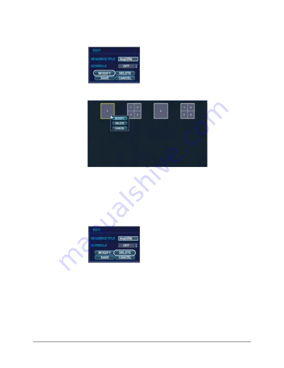
Figure 2-31

Sequence EDIT Window

2. Click 

MODIFY

. The Sequence window opens. 

Figure 2-32

Sequence Window

3. Right-click on a step in the sequence, then choose to modify it, to delete it, or to 

cancel this action. 

4. Make the changes, then click 

CONFIRM

. Click 

CLOSE

 to close that sequence. 

Deleting a Sequence

1. Double-click in the 

List

 column the sequence you want to delete. 

The EDIT window appears. 

Figure 2-33

Sequence EDIT Window

2. Click 

DELETE

. That sequence disappears from the list of sequences. 

Configuring the Spot-Out Display

This DVR has a single spot monitor output. You can assign the SPOT OUT display for each 
channel. Using this screen, you can configure which cameras are displayed at the spot 
output. 
1. Click 

SPOT OUT

 on the left side of the DISPLAY window. The SPOT OUT menu 

appears.

Summary of Contents for HREP16

Page 1: ...Document 800 06847 Rev B 08 10 User Guide HREP4 HREP8 HREP16 4 8 16 Channel Models Color Digital Video Recorder ...

Page 2: ......

Page 3: ...User Guide ...

Page 4: ...de level 1 headers Edited the Marking Recorded Video and Archiving sections so that they are more thorough Replaced Fig 2 21 with corrected images Updated screen shots in Chapters 2 and 3 Added Configuring a PTZ Tour in Configuring the PTZ Setup Moved the Configuring PTZ Cameras section into the System Setup section Added new sections in the Configuring Display Sequence section Activating Modifyin...

Page 5: ...19 Typical System Setup 21 2 Installation 23 Front Panel Description 23 Rear Panel Description 25 Remote Control 26 Setting the DVR ID Using the Remote Control 27 Returning to the Original ID Settings 27 DVR Operation 27 Making the connections 27 Powering up the DVR 27 Logging On 28 Live Display 30 Controlling PTZ Cameras 30 Using Digital Zoom 31 Viewing the Log 32 Panic Recording 32 Using the Qui...

Page 6: ...T to See Archived Data 79 4 Using the Web Remote Viewer 81 Preparing for an Internet Connection 81 Port Forwarding 81 Minimum Internet Requirements 81 Connecting to the Internet 82 Live Mode 85 Searching for Recorded Video 87 Searching by Timeline 87 Searching by Event 88 Setup Mode 89 Using an Internet Connection to Configure a Camera 90 Configuring Motion Detection 90 Configuring the On Screen D...

Page 7: ...34 Figure 2 14 MAIN Menu Window 34 Figure 2 15 Camera Setup Window 35 Figure 2 16 COLOR SETUP Menu 36 Figure 2 17 Example of Configuring the Color Setup Window 36 Figure 2 18 PTZ SETUP Menu 37 Figure 2 19 PTZ Property Window 37 Figure 2 20 PTZ Window 38 Figure 2 21 PTZ Parameter Window 39 Figure 2 22 PTZ TOUR Window 39 Figure 2 23 Motion Sensor Menu 40 Figure 2 24 Configuring the Motion Sensor Are...

Page 8: ...2 55 E MAIL NOTIFICATION Setup Menu 62 Figure 2 56 DISK MANAGEMENT Setup Window 63 Figure 2 57 SETUP Window 64 Figure 2 58 RECORDING Setup Window 64 Figure 2 59 CONTINUOUS MOTION RECORDING Setup Window 65 Figure 2 60 Configuring SIZE FPS QUALITY Time Bar 66 Figure 2 61 Configuring SIZE FPS QUALITY Window 66 Figure 2 62 Configuring the Schedule 68 Figure 2 63 Selected Channels and Time 68 Figure 2 ...

Page 9: ...arch Query Results 89 Figure 4 12 Internet Connection Camera Setup Window 90 Figure 4 13 Motion Setting Configuration Window 91 Figure 4 14 OSD Setting Window 91 Figure 4 15 Monitor Setting 92 Figure 4 16 Audio Buzzer Setting Window 92 Figure 4 17 Date Time Setting Window 93 Figure 4 18 Continuous Motion Recording Setting Window 94 Figure 4 19 User Authority Setting Window 94 Figure 4 20 IP Setup ...

Page 10: ...10 Figures ...

Page 11: ...2 2 Rear Panel Description 25 Table 2 3 Quick Menu 33 Table 2 4 Configurations for Continuous Motion Recording 67 Table 2 5 Color Codes for the Recording Modes 69 Table 3 1 Recording Type Indicator Colors 72 Table 3 2 AVI ARCHIVING LIST Functions 80 Table 4 1 Internet RA Minimum PC Requirements 81 Table 4 2 Live Mode Functions 85 ...

Page 12: ...12 Tables ...

Page 13: ...xes Chapter 1 Introduction introduces the HREP DVR features and a typical setup Chapter 2 Installation provides procedures for installing and configuring your DVR Chapter 3 DVR Operation explains how to use your DVR Chapter 4 Using the Web Remote Viewer explains how to use your DVR over the internet Chapter 5 Watermark Process explains the watermark process which identifies whether an image has be...

Page 14: ...A digital apparatus complies with Canadian ICES 003 Cet appareil numérique de la Classe A est conforme à la norme NMB 003 du Canada Manufacturer s Declaration of Conformance North America The equipment supplied with this guide conforms to UL 60950 1 and CSA C22 2 No 60950 1 Europe The manufacturer declares that the equipment supplied with this guide is compliant with the essential protection requi...

Page 15: ... not fit into your outlet consult an electrician for replacement of the obsolete outlet Protect the power cord from being walked on or pinched particularly at plugs convenience receptacles and the point where they exit from the apparatus Only use the attachments accessories specified by the manufacturer Use only with a cart stand tripod bracket or table specified by the manufacturer or sold with t...

Page 16: ...thorization RMA number Be sure to have the model number serial number and the nature of the problem available for the technical service representative Prior authorization must be obtained for all returns exchanges or credits Items shipped to Honeywell without a clearly identified Return Merchandise Authorization RMA Typographical Conventions This document uses the following typographical conventio...

Page 17: ...turn key Enter the password Menu titles and other items you select Double click Open from the File menu Buttons you click to perform actions Click Exit to close the program Italic Placeholders words that vary depending on the situation user name Cross reference to external source Refer to the System Administrator Guide Cross reference within document See Chapter 2 Installation Font What it represe...

Page 18: ...18 ...

Page 19: ... abrasive cleaners Do not attempt to service or repair the DVR Opening or removing the cover may expose dangerous voltages or other hazards Refer all servicing to qualified service personnel Features Your color digital video recorder DVR provides recording capabilities for 4 8 or 16 camera inputs depending on your model It provides exceptional picture quality in both live and playback modes and of...

Page 20: ...e DVR also has a panic recording feature from the front panel or external input which overrides all other recording settings to provide the best quality recording in the event of an emergency PTZ CONTROL Full PTZ control is available from the front panel or remote connection and a wide number of speed dome protocols are supported Protocols can be set individually for each channel and PTZ speed can...

Page 21: ...HREP Color Digital Video Recorder User Guide Document 800 06847 Rev B 21 08 10 Typical System Setup Figure 1 1 Typical System Setup ...

Page 22: ...22 Introduction ...

Page 23: ...device B Status LED Power Recording including pre recording Network Alarm C POWER Turn ON OFF the system power D Cursor Keys Allow you to navigate through the menus Increases reverse playback speed Zoom for controlling PTZ cameras Starts reverse playback Pauses playback Parameter for PTZ cameras Starts forward playback Increases forward playback speed Zoom for controlling PTZ cameras A B C D E E F...

Page 24: ...rolling PTZ cameras DISPLAY Selects various display modes in live display and playback Focus for controlling PTZ cameras FREEZE Displays the freeze image in live view Focus for controlling PTZ cameras PANIC Records using the Panic Recording setup Iris for controlling PTZ cameras SEQUENCE Changes to the Sequence screen Iris for controlling PTZ cameras G Shuttle Wheel Used to quickly adjust the play...

Page 25: ...ut type E ALARM INPUTS Up to four alarm inputs can be connected and configured as high or low inputs with common ground RELAY OUTPUT One alarm output can be connected and configured as high or low output with a common ground F RS485 Connect a PTZ camera G LAN LAN connection to a router or internal network H DVI DVI main monitor connection to a PC monitor or a plasma screen Note If you want to conn...

Page 26: ...n Off ID button Select DVR ID RETURN Cancel Deselect Previous screen SETUP Open System Setup menu Channel selection buttons AUDIO Not supported ENTER Apply Select Go to next screen Navigation Buttons Used for playback control menu navigation and PTZ focus control DISP Change the display screen SEARCH Go to Search mode PTZ Go to PTZ menu PANIC Start panic recording KEYLOCK Lock the Remote Front key...

Page 27: ...nal ID Settings 1 Press the ID button again 2 Enter 255 then press the RETURN button on the remote control DVR Operation Making the connections Connect up to 16 camera inputs DVR model dependent monitors to the DVR using the Composite or DVI connections power to the DVR The DVR checks for proper power connection and then emits two beeps Powering up the DVR Press the POWER button on the front panel...

Page 28: ...rive Logging On After startup diagnostics are complete you must log onto the system The default user name is ADMIN Figure 2 5 Log On Screen Enter the default password 1234 using the channel selection buttons then press ENTER The DVR begins normal operation and shows the default display of 4 8 or 16 channels depending on your DVR model ...

Page 29: ... red square and letter C in the top right corner of each channel display indicates that the channel is in Continuous recording mode Control Bar All menus can be controlled with the Control bar using either the front panel buttons or a mouse not included Figure 2 7 Control Bar Note This User Guide contains instructions for using the front panel controls for configuration and operation unless otherw...

Page 30: ... menu Sequencing the Channels Click SEQ in the display popup menu Each channel is shown in full screen for a set period of time before switching to the next channel in the sequence Click again to stop the sequence on that current channel More complex sequences can be programmed through the Setup menu See Configuring the Display Sequence on page 42 Controlling PTZ Cameras 1 Navigate to PTZ in the C...

Page 31: ...ontroller controls for PTZ cameras Using Digital Zoom When viewing a channel in full screen you can use your HREP8 or HREP16 to zoom in to a particular area by up to 8 times The HREP4 supports 2 times digital zoom without a small picture in picture window Select the desired channel then navigate to ZOOM on the control bar and then click Figure 2 10 Example of the Digital Zoom Select the camera cha...

Page 32: ...EC in the control bar then click to start and stop Panic recording The REC button changes to a red square with a P to indicate that panic recording has started Use the RECORD SETUP window to configure the Panic recording settings See Configuring Panic Recording on page 70 Using the Quick Menu Accessing the Quick Menu Click the right mouse button in any of the live channels to open a Quick menu of ...

Page 33: ...annels on your HREP4 Even though other channels show live display this particular channel display is stopped Right click and then select FREEZE OFF to exit the freeze mode PTZ See Controlling PTZ Cameras on page 30 ZOOM See Using Digital Zoom on page 31 PLAYBACK You can select a go back duration 10 20 or 30 seconds ago or 1 minute ago or a specific time and date for immediate play back If you sele...

Page 34: ... MAIN Menu Window Use the cursor keys and ENTER and RETURN to navigate the MAIN setup menu Use to select and change a particular item Use to cancel a change or exit from a particular setup screen Select SYSTEM SETUP and then press to set up all the main system functions Configuring the Camera Configuring the Camera Setup Select CAMERA in the Main system setup window then click The CAMERA setup win...

Page 35: ... COVERT is turned ON the camera image is not displayed in Live display but the DVR continues to record the video When COVERT is turned ON and a Manager or User account is logged on the live channel does not display in the Web Client display But when an Admin account is logged on the live channel displays AUDIO Choose the audio recording channel Configuring the Color Setup Click COLOR SETUP on the ...

Page 36: ... Select a channel and click to select that channel for configuration The selected channel displays full screen Figure 2 17 Example of Configuring the Color Setup Window Click the Up Down arrows to configure the brightness contrast tint and color Click when all changes are complete and you want to escape this window ...

Page 37: ... PROTOCOL and BAUD RATE columns to configure them Use the to change the following values Configuring Details for PTZ Cameras Click DETAIL on the PTZ SETUP menu The PTZ Property window appears Figure 2 19 PTZ Property Window ADDRESS The unique ID of the PTZ device PROTOCOL The protocol of the PTZ device BAUD RATE The baud rate of the PTZ device DETAIL Detailed settings for the PTZ device See Config...

Page 38: ... in the Control bar then click to select The PTZ window appears Figure 2 20 PTZ Window 2 Select the camera by channel 3 Select a preset number 4 Use the arrow buttons to reposition the PTZ camera field of view 5 Use ZOOM FOCUS and IRIS to change the current camera view 6 Click PARAMETER to configure PTZ camera parameters 7 Click SET to save the settings See Table 2 1 on page 23 for descriptions of...

Page 39: ...igure 2 22 PTZ TOUR Window 2 Click next to MODE to select AUTO to enable PTZ Tour setup 3 Click on the up down arrows under the PRESET NO column to select a preset from 1 to 16 then click on the up down arrows under the DWELL TIME to select a dwell time from 1 to 20 seconds Note Even though you can configure up to 255 presets using the PTZ menu for configuring a PTZ tour you can select from only p...

Page 40: ...nfiguring the Motion Sensor Area Click the AREA SETUP button next to your desired channel A grid appears over the video image for the chosen channel Figure 2 24 Configuring the Motion Sensor Area To quickly select or deselect the entire grid right click on the screen then select SELECT ALL or DESELECT ALL Configuring the Display Select DISPLAY in the Main system setup window and then click The DIS...

Page 41: ...it disappears and the date time displays CAMERA TITLE Enable disable the display of the camera title RECORDING MODE ICON Choose whether the DVR recording status shows at the top right of each channel display window BORDER Choose whether there is a border around each channel when in multi screen display mode MOTION SENSOR DISPLAY This function provides a visual indication when and where motion is s...

Page 42: ... channels in D1 resolution 704x576 to prevent shudder during playback ALARM POP UP MODE Set to ON so that the associated channel displays in full screen when an alarm is triggered ALARM POP UP DWELL Choose how long the full screen popup displays after an alarm is triggered If the alarm condition continues then the popup screen displays constantly MOTION POP UP MODE When set to ON motion detection ...

Page 43: ...ne a custom sequence using mixed multi screen views and any desired channels Adding a Sequence 1 Click ADD at the bottom of the SEQUENCE menu The Add window appears Figure 2 28 Add Sequence Window 2 Click to bring up the virtual keyboard to change the Sequence Title from DEFAULT Use the virtual keyboard to enter a name or reference number for the new sequence 3 Turn the SCHEDULE ON or OFF 4 Select...

Page 44: ...FIGURE panel then click CONFIRM Click ADD to add another mode Double click the current sequence to modify it The SEQUENCE SETUP window reappears Click CLOSE when you are finished Activating a Sequence Press SEQ on the front panel or select Sequence from the control bar when in live view See Figure 2 8 on page 30 Modifying a Sequence 1 Double click in the List column the sequence you want to modify...

Page 45: ...LOSE to close that sequence Deleting a Sequence 1 Double click in the List column the sequence you want to delete The EDIT window appears Figure 2 33 Sequence EDIT Window 2 Click DELETE That sequence disappears from the list of sequences Configuring the Spot Out Display This DVR has a single spot monitor output You can assign the SPOT OUT display for each channel Using this screen you can configur...

Page 46: ...ow appears Figure 2 35 SPOT OUT Edit Window 4 Click to bring up the virtual keyboard to change the Spot Title from DEFAULT Use the virtual keyboard to enter a name or reference number for the new sequence 5 Turn the SCHEDULE ON or OFF 6 Click MODIFY then double click the current display to modify it This window appears 7 Click ADD The Spot Sequence Setup window appears ...

Page 47: ...en click CONFIRM Note You can choose from Single or Quad display only Click ADD to add another mode Double click the current sequence to modify it The SEQUENCE SETUP window appears Click CLOSE when you are finished The new sequence is now saved and can be started by pressing SEQ when in live view Configuring Sound Settings Select SOUND in the Main system setup window then press The SOUND setup win...

Page 48: ...guring System Settings Select SYSTEM in the Main system setup window then click The SYSTEM setup window opens Figure 2 38 System Setup Window LIVE AUDIO When ON the selected audio channel can be monitored on the AUDIO OUTPUT DEFAULT AUDIO CHANNEL Specify which one of the four AUDIO INPUTS is routed to the AUDIO OUTPUT NETWORK AUDIO TX When ON live audio is transmitted to a remote PC connection Rec...

Page 49: ...e 2 39 System Management Window 2 Click INFO The SYSTEM INFORMATION window appears Figure 2 40 SYSTEM INFORMATION Window DATE TIME Set the current date and time DATE FORMAT Determine how the date is displayed TIME FORMAT Determine how the time is displayed NETWORK TIME SERVER If the DVR is connected to the internet the time and date can be accurately set by selecting SYNC and pressing TIME ZONE Se...

Page 50: ...econd value shows the total hard drive capacity installed IP Address Shows either the manual IP address entered in NETWORK setup or the IP address assigned by a DHCP server if enabled MAC Address Shows the MAC Media Access Control address of the DVR It is unique no other network device has this MAC address DDNS DOMAIN NAME If DDNS is enabled the host DDNS server is specified here RTSP SERVICE PORT...

Page 51: ...RY DEFAULT Use to restore factory default settings SYSTEM DATA System settings can be saved to a USB memory stick The settings can be reloaded in case of accidental factory default or can be transferred to another DVR if multiple units need to be installed with the same settings All information is saved apart from the network settings and the system name PASSWORD Activates deactivates the need for...

Page 52: ...s for a total of eight and edit existing user details Modifying User Details 1 Highlight the user with the green cursor press The Edit window appears Figure 2 44 Edit User Window 2 Double click each of the following fields to configure them USER ID Use the virtual keyboard to edit the user ID up to ten characters PASSWORD Use the virtual keyboard to change the password up to eight characters ...

Page 53: ...UP Assign the user to one of three groups ADMIN MANAGER or USER E MAIL Enter the user s e mail address up to 64 characters if e mail notification is required E MAIL NOTIFICATION Enable or disable e mail notifications for the specified user USER ID Use the virtual keyboard to edit the user ID up to ten characters PASSWORD Use the virtual keyboard to change the password up to eight characters GROUP ...

Page 54: ...e System Management Settings See Configuring System Management Settings on page 49 Configuring User Log Out 1 Click LOG OUT on the left side of the USER window The LOG OUT menu appears Figure 2 47 LOG OUT Menu 2 Use the to configure the following settings Configuring the Network Settings Select NETWORK in the Main system setup window then click The NETWORK setup window opens AUTO LOGOUT Enables di...

Page 55: ...ddress automatically if it is connected to a DHCP server or router IP ADDRESS If DHCP is not being used then the IP address can be manually set GATEWAY If DHCP is not being used then the gateway IP address can be manually set SUBNET MASK If DHCP is not being used then the subnet mast can be manually set 1st DNS SERVER If DHCP is not being used then the first DNS server can be manually set 2nd DNS ...

Page 56: ...function When you click the AUTO PORT the port forwarding is automatically set up You can also delete a port and test a port s functionality from here WEB SERVER PORT If connected then the router supports UPNP Universal plug and play function When you click the AUTO PORT the port forwarding is automatically set up You can also delete a port from here This is the port number that the DVR uses to su...

Page 57: ...k E MAIL on the left side of the NETWORK window The E MAIL setup menu appears Figure 2 50 E MAIL Setup Menu 2 Configure the following settings SERVER The SMTP outbound e mail server that should be used to send e mail notifications PORT The outbound e mail port number SECURITY Set to OFF if the SERVER does not require a user name and password to connect USER Enter a user name to identify the DVR in...

Page 58: ...ide of the EVENT SENSOR window if it is not already selected The HDD EVENT setup menu appears See Figure 2 51 2 Configure the DVR to monitor the hard drives and detect problems Configuring Alarm Input 1 Click ALARM INPUT on the left side of the EVENT SENSOR window The ALARM INPUT setup menu appears S M A R T HDD ALARM Enables S M A R T disk monitoring CHECK INTERVAL Adjust the interval as desired ...

Page 59: ...arm inputs Configuring Alarm Output 1 Click ALARM OUTPUT on the left side of the EVENT SENSOR window The ALARM OUTPUT setup menu appears Figure 2 53 ALARM OUTPUT Setup Menu The settings you choose for Alarm Output determine the behaviors and actions that will trigger each of the alarm outputs on your DVR OPERATION Enable disable alarm inputs TYPE Set alarm inputs to N O normally open or N C normal...

Page 60: ...he output is active only when the trigger criteria are present or LATCHED the output is active for a set period of time after a trigger DURATION In LATCHED mode this is the time that the alarm output remains active after it has been triggered TYPE Select from HIGH 0V to 5V when activated or LOW 5V to 0V when activated HDD EVENT Determines whether a hard drive event triggers the alarm output ALARM ...

Page 61: ...w The E MAIL NOTIFICATION setup menu appears OPERATION Enable disable the internal buzzer HDD EVENT Determines whether a hard drive event triggers the buzzer MODE Select from TRANSPARENT the buzzer sounds only when the trigger criteria are present or LATCHED the buzzer sounds for a set period of time after a trigger DURATION In LATCHED mode this is the time that the alarm output remains active aft...

Page 62: ...il notification SETUP CHANGE Configure whether a setup change triggers an e mail notification HDD EVENT Configure whether a hard drive event triggers an e mail notification BOOTING EVENT Configure whether a booting event triggers an e mail notification ALARM Configure whether alarm inputs trigger an e mail notification VIDEO LOSS Configure whether video loss on any of the selected channels trigger...

Page 63: ... to comply with data protection laws for example Recording can be limited to 12 hours 1 day 2 days 3 days 1 week or one month When the DVR has this amount of footage stored it will start to overwrite the earliest recorded footage OVERWRITE When ON the DVR starts overwriting the earliest recorded footage once the hard drive becomes full In this case the percentage of hard drive used shown in live d...

Page 64: ...58 SCHEDULE MODE Select either DAILY one schedule applies to every day of the week or WEEKLY each day of the week has its own schedule PRE EVENT RECORDING TIME When the DVR is not in continuous recording mode this setting determines the amount of time that is always recorded before an event motion detection alarm input for example occurs POST EVEN RECORDING TIME When the DVR is not in continuous r...

Page 65: ...ettings There are two tabs for configuration Configuring SIZE FPS QUALITY 1 If it is not already selected select SIZE FPS QUALITY on the CONTINUOUS MOTION RECORDING setup menu The SIZE FPS QUALITY setup menu opens SIZE FPS QUALITY Recording settings for each channel can be defined across a 24 hour period in blocks for example between 09 00 and 18 00 or for each individual hour Note When SCHEDULE M...

Page 66: ...Bar Each green cursor box represents one hour The table below the time bar shows the recording settings for this time period 2 Select a length of time on the schedule A new configuration window opens Figure 2 61 Configuring SIZE FPS QUALITY Window Frames available ...

Page 67: ... at 352x240 resolution As the settings are adjusted the frames available at the bottom left displays the number of available frames still remaining and must always be zero or higher See Configuring SIZE FPS QUALITY Window on page 66 If while changing recording settings this figure becomes negative then the recording resolutions and or frame rates must be lowered to increase the frames available va...

Page 68: ...onfiguring the Schedule 2 To change the SCHEDULE settings press again The schedule box highlights in green 3 Press and hold then use the cursor keys to drag and select the recording time and the channels Figure 2 63 Selected Channels and Time 4 Click again when you have made your selection The EVENT window opens ...

Page 69: ...G See Configuring Continuous Motion Recording on page 65 for more information SIZE FPS QUALITY and SCHEDULE Configuration Fields Table 2 5 Color Codes for the Recording Modes Block Color Recording Mode PINK No scheduled or motion recording SKY BLUE Continuous recording BLUE Recording triggered by motion detection YELLOW Continuous recording and recording triggered by motion detection SIZE FPS QUAL...

Page 70: ... Figure 2 65 PANIC RECORDING Setup Window During Panic Recording the DVR overrides all other recording settings and uses the settings configured here to record continuously on all channels Press to enable configuration of SIZE FPS QUALITY and AUDIO for each channel during Panic Recording A new configuration window opens Use the cursor keys to navigate to the configurable fields Press to enable the...

Page 71: ...section of recorded footage To prevent unauthorized viewing of footage only users with ADMIN or MANAGER user levels can play back footage Searching for Video 1 Log on as ADMIN See Logging On on page 28 2 Navigate to SEARCH on the control panel then click The SEARCH window appears Figure 3 1 SEARCH Window Calendar Timeline ...

Page 72: ...able the SEARCH BY DATE TIME window 2 Use the cursor keys to highlight the calendar then press to select 3 Use the cursor keys to navigate to a day The timeline display changes to show recorded footage for the selected day 4 Press to select a day The timeline field becomes active 5 Use the cursor keys to drag the timeline to select the desired time segment then press to select 6 Click PANO then pr...

Page 73: ...Select a channel and you can play back the recorded video at a speed of up to 64x See Changing the Playback Speed on page 74 for more information Searching in MULTI VIEW Mode Press after selecting PLAY The playback window appears Channel Time frame CH1 00 00 03 00 CH2 03 00 06 00 CH3 06 00 09 00 CH4 09 00 12 00 CH5 12 00 15 00 CH6 15 00 18 00 CH7 18 00 21 00 CH8 21 00 24 00 ...

Page 74: ...mats Changing the Playback Speed During playback turning the SHUTTLE WHEEL see Figure 2 1 steadily clockwise increases the playback speed by up to 64 times During playback turning the SHUTTLE WHEEL steadily counter clockwise will reverse playback with an increasing speed up to 64 times Viewing Footage Frame by Frame When playback is paused use the JOG RING see Figure 2 1 or the fast forward or fas...

Page 75: ...rchiving to end The INFORMATION window appears again 4 Click one of the following buttons Note You must reserve data so it can be retrieved later for Archiving Note Reserved data will be reserved on the hard disk drive You can use the RESERVED DATA MANAGEMENT function on the ARCHIVING menu to see the reserved data See Using RESERVED DATA MANAGEMENT to See Archived Data on page 79 Button Function R...

Page 76: ... Live View press again Searching for Events The DVR event log stores events such as motion and alarm activated recording and video loss 1 Log on as ADMIN See Logging On on page 28 2 Navigate to SEARCH on the control panel then click The SEARCH window appears Figure 3 6 SEARCH Window 3 Navigate to SEARCH BY EVENT then click The SEARCH BY EVENT window appears ...

Page 77: ...ick SEARCH to begin the search Playing Event Footage Use the cursor keys to navigate the search log see Figure 3 7 then click to select an event The playback window appears Figure 3 8 Playback Window Playback begins with the time of the selected event and continues until you stop playback You can use the SHUTTLE WHEEL JOG RING and playback buttons during playback Search button Search log ...

Page 78: ...can archive data Using NEW ARCHIVING to Archive Data 1 Press BACKUP on the front panel or use a mouse click ARCH on the control bar The ARCHIVING window appears Figure 3 9 ARCHIVING Window 2 Query to find recorded video a Select the channel s you want to query by clicking on the box to enable or disable the check mark b Select a time by clicking on the time field you want to change then using the ...

Page 79: ...ow 5 Select a DEVICE and a BURNING TYPE then click START in the BURNING menu Using RESERVED DATA MANAGEMENT to See Archived Data 1 Press BACKUP on the front panel or use a mouse click ARCH on the control bar The ARCHIVING window appears See Figure 3 9 2 Click RESERVED DATA MANAGEMENT on the left side of the ARCHIVING window The RESERVED DATA MANAGEMENT window appears Figure 3 11 RESERVED DATA MANA...

Page 80: ...ecorded Video During Playback for Archiving on page 75 Select a clip by name in the AVI ARCHIVE LIST then click BURN 3 Select a DEVICE and a BURNING TYPE then click START in the BURNING menu Table 3 2 AVI ARCHIVING LIST Functions Button Function INFORMATION View the detailed information of reserved AVI data DELETE Delete the reserved AVI data BURN Backup the selected AVI data ...

Page 81: ...o your Router manual for port forwarding settings Minimum Internet Requirements Table 4 1 Internet RA Minimum PC Requirements CPU P4 3 0 or higher RAM 512MB or higher VGA Geforce MS 400 Radeon 7500 or higher Geforce 8 series or higher VGA Memory 64MB Monitor 1280x1024 OS Microsoft Windows XP2 IE Version IE6 0 or higher other browsers Firefox for example might not operate properly Network 100Mbps D...

Page 82: ...sing the DDNS services enter the URL as shown below http 1234 dvrlink net 8080 webport 8080 or http 1234 dvrlink net webport 80 The Windows Security window opens Figure 4 1 Entering the User Name and Password for Internet Connection 3 Enter the Default ID ADMIN and password 1234 then click OK The ATM Windows Internet Explorer Add On option window opens ...

Page 83: ...tall ActiveX An ActiveX Installation window opens Figure 4 3 ActiveX Installation Window 5 Click Install to install ActiveX Enabling the Installation of ActiveX You might not be able to install ActiveX due to some Internet Explorer security settings To change these security settings go to Tools Internet Options Security Custom Level The Internet Options window opens ...

Page 84: ...Internet Options Window in IE 6 Click Custom level The Security Settings Trusted Sites Zone window appears Figure 4 5 Security Settings Trusted Sites Zone Window 7 Select Enable for all ActiveX related options then click OK to save the changes ...

Page 85: ...n of the screen in Live view mode Select from 1 4 8 9 and 16 screens Move to next N cameras for example from ch1 4 to ch5 8 in 2x2 view Move to the next camera Display Full Screen Manually select the live channel Activate Mic to send sound to the DVR Turn On Off sound from the DVR Save the live image Print the current screen Snapshot the current screen Setup Render Save Folder and select which aud...

Page 86: ...n an Alarm Output is detected Refresh Time Set the interval of Refresh for the camera status and log Reload Instantly refresh the camera status and log Log Displays all system logs in real time PTZ Allows you to control connected PTZ cameras Table 4 2 Live Mode Functions Live Mode Function Description Pattern Move a PTZ camera through several preset positions Preset Set the position of a PTZ camer...

Page 87: ...arch window appears Figure 4 7 Internet Search Window In this window you can do the following functions 2 Click Search By Time if it isn t already selected Function Description Refresh Refresh the data in the recording table Play Play the data recorded from the system Backup Save to the local computer an AVI video clip file from video that was recorded at the remote site DVR ...

Page 88: ...able or set an exact time then click Play 4 Click Backup and the Backup configuration window opens Figure 4 9 Backup Configuration Window Searching by Event 1 Click Search By Event The Search By Event window opens Figure 4 10 Search By Event Window 2 Select the type s of event s you want to search ...

Page 89: ...ck Search The results of the search display Figure 4 11 Event Search Query Results Setup Mode In the Setup window in the field on the left you can access configuration menus for configuring Cameras The display Sound parameters System setup Recording parameters Users The network connection Sensors Click Setup in the Live mode window The Setup Camera Setting window displays ...

Page 90: ...amera You can configure a camera s title live color display PTZ setup and motion detection settings 1 Click Camera again under Camera in the field on the left Figure 4 12 appears 2 Make your configuration selections and then click Ok to save Configuring Motion Detection 1 Click Motion under Camera The Motion Setting window opens ...

Page 91: ...sensitivity level 3 Drag your mouse on the image to select a detection area 4 Click OK See Configuring PTZ Camera Parameters on page 31 for more information Configuring the On Screen Display You can choose which text items display over the image Click OSD under Display in the field on the left The OSD Setting window opens Figure 4 14 OSD Setting Window ...

Page 92: ...on the left The Monitor Setting window opens Figure 4 15 Monitor Setting You can set the dwell time for a sequence or spot and for the pop up functions See Configuring the Monitor Display on page 40 for more information Configuring the Sound Settings Click Audio Buzzer under Sound in the field on the left The Audio and Buzzer Setting window opens Figure 4 16 Audio Buzzer Setting Window ...

Page 93: ...uring the System Setup Click System in the field on the left The Date Time Setting window opens Figure 4 17 Date Time Setting Window You can configure the date and time for the system check system information and configure the system ID serial port protocol and baud rate for the control device See Configuring System Settings on page 46 for more information Configuring the Recording Settings Click ...

Page 94: ...to configuring system settings See Configuring the Users on page 49 for more information Configuring Users Click User in the field on the left The User Authority Setting window opens Figure 4 19 User Authority Setting Window You can add a user select a user s authority level and configure the user s log out time See Configuring the Users on page 49 for more information ...

Page 95: ...ormation and selectable speed level You cannot change IP settings The network IP can be set only on the DVR See Configuring the Network Settings on page 52 for more information Configuring E mail Notification Click E mail under Network in the field on the left The E mail Setting window opens Figure 4 21 E mail Setting Window You can enter the SMTP server details to set up for e mail notification S...

Page 96: ... 22 Alarm Output Setting Window Users with ADMIN privileges can set all device options for Alarm in out and buzzer out for event notification HDD event alarm input alarm output buzzer out and e mail notification See Configuring Alarm Setup on page 67 for more information Getting Information Click on Information and view the information about your DVR ...

Page 97: ...HREP Color Digital Video Recorder User Guide Document 800 06847 Rev B 97 08 10 Figure 4 23 Information About Your DVR ...

Page 98: ...98 Using the Web Remote Viewer ...

Page 99: ...s that were burned to CD DVD or to USB media using the Backup Archive Burn process from the front panel of the DVR 1 Open the backup data from the device and then run the bplayer which is included in the backup folder Figure 5 1 bplayer 2 Click the Open file button and open the backup file ...

Page 100: ...100 Watermark Process Figure 5 2 Opening the Backup File 3 Click Yes when the Checking the watermark message appears after opening the backup file Figure 5 3 Checking the Watermark Message ...

Page 101: ...HREP Color Digital Video Recorder User Guide Document 800 06847 Rev B 101 08 10 The file opens Note If the backed up AVI file has been modified a Verification Failed message appears ...

Page 102: ...102 Watermark Process ...

Page 103: ......

Page 104: ...31 299 410 200 Honeywell Systems Group Deutschland Johannes Mauthe Straße 14 D 72458 Albstadt Germany www honeywell com security de 49 74 31 8 01 0 Honeywell Systems Group France Immeuble Lavoisier Parc de Haute Technologie 3 7 rue Georges Besse 92160 Antony France www honeywell com security fr 33 0 1 40 96 20 50 Honeywell Systems Group Italia SpA Via della Resistenza 53 59 20090 Buccinasco Milan ...

Reviews: