


HPF902ULADA Distributed Power Module Installation Manual
4-13
3.
Connect the red wire from the B terminal to the positive (+) side of battery #1.
Figure 4-6 Battery Connection
4.8
DIP Switch Settings
A 7-position DIP switch on the HPF902ULADA board allows you to select the following:
•
How long the HPF902ULADA will wait before indicating a loss of AC.
•
Which input (Input 1 or Input 2) will control the NACs.
•
Which NACs to wire as Class A and Class B.
•
Auxiliary power state.
•
Which NACs to operate as steady, ANSI temporal, or sync. outputs
Refer to Figure 4-2 for the location of the DIP switch on the HPF902ULADA board.
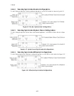
4.8.1
Selecting the Standard Input/Output Configurations
Figure 4-7 and Figure 4-8 show the position of each switch for the non-synchronized input and output
configurations. The position of Switches 4 and 5 does not affect the relationship of inputs to outputs.
Note:
The HPF902ULADA checks switches 1, 2, 3, and 6 only when powering up the HPF902ULADA. If you change these
switch settings, you must remove both the AC power and the battery to make the HPF902ULADA recognize the new
Summary of Contents for HPF902ULADA
Page 39: ......