


Trouble Operation
Operating Instructions
The FACP performs the following functions at regular intervals in Normal mode:
Monitors AC input voltage and battery voltage
Monitors and reports status option cards and control panel
Refreshes LCD display and updates time
Scans control panel keypad for key presses
Tests memory
Updates and reads all communications busses (EIA-485, etc.)
i
3
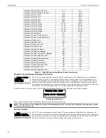
smoke detectors will be polled for maintenance and freeze conditions on initial entry into Normal mode. Thereafter, each
device will be polled every hour for freeze and every four hours for maintenance conditions
4.4 Trouble Operation
With no alarms in the system, the detection of a trouble will cause the following:
•
The piezo to pulse 1 second On and 1 second Off
•
The system Trouble LED to flash one second On and one second Off
•
The trouble relay to activate
•
TROUBL
with device type, adjective/noun, address and trouble description will appear on the LCD display
•
The same message, along with the time and date, is sent to the optional printer and the history buffer.
•
Communicate the trouble conditions to the Central Station
•
Terminate upload or download communications
Note that specific troubles will initiate additional actions; for example, loss of AC power will turn off the AC Power LED, etc.
Input Zone
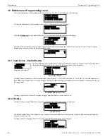
For Input Zones, the following is a typical message that could appear on the LCD display for a device trouble:
The information displayed in the above example provides the following information:
•
First line in display:
– The type of event; in this example
OPEN
indicating a circuit trouble
– Device type identifier; in this example,
PULL STATION
indicates a manual device. Other device type identifiers which can be
displayed include
SMOKE
for Smoke Detector,
HEAT
for Heat Detector, etc.
•
Second line in display:
– <ADJ>; refers to the user programmed adjective descriptor from library list resident in the control panel or custom entry via PC.
– <NOUN>; refers to the user programmed noun descriptor from library list resident in the control panel or custom entry via PC.
•
Third line in display indicates Zone and the fault condition. Other possible troubles include:
OPEN
- indicating an open circuit
DIRTY
- maintenance alert indicating that an i
3
detector is near but below the allowed alarm limit and is in need of maintenance
before the performance is compromised
•
Fourth line in display:
– Time; the current time in this example is
10:00A
which represents 10:00 AM
– Date; the current month, day and year in this example is
06
for June,
09
for the 9th day of the month and
18
for the year 2018
Pressing the
Acknowledge/Step
or
Alarm Silence
key will cause the pulsing piezo to silence and the system Trouble LED to change from
flashing to on steady. This block acknowledgment occurs regardless of the number of troubles, alarms and supervisory events active in
the system. When the
Acknowledge/Step
key is pressed and at least one new alarm or trouble exists in the system, the ‘acknowledge’
message is sent to the printer and history file. If the trouble clears, either before or after the
Acknowledge/Step
key is pressed, the ‘clear
trouble’ message is sent to the printer and history file.
If all troubles clear and there are no supervisory or fire conditions active in the system, the system returns to normal mode operation and
the
System All Normal
message is shown on the LCD display and sent to the history and printer files. The auto-restore feature will restore
cleared troubles even if the troubles were never acknowledged. Note that pressing the
Alarm Silence
key when only troubles exist in the
system will have the same effect as pressing the
Acknowledge/Step
key except the Alarm Silenced LED will light.
4.5 Alarm Operation
Alarm operation is similar to trouble operation with the following differences:
•
The piezo sounder produces a steady output as opposed to a pulsed output
•
The Fire Alarm LED flashes 1 second On and 1 second Off
•
The LCD displays
Alarm
along with the device name, type, adjective/noun, associated zones and time/date
NOTE:
To ensure that the system is functioning properly, the FACP will perform a freeze check five minutes after the panel is reset,
followed by a maintenance check. If there is no freeze or maintenance condition, the panel will continue to monitor for freeze conditions
every hour and maintenance conditions every four hours.
TROUBL PULL STATION
<ADJ> <NOUN>
ZONE 10 OPEN FAULT
10:00A 060918
GF505 & GF510 Manual —
P/N 53164:B5 6/12/2018
87