


option called Ignore extended diagnostic overflow (IGNOREXTDIAGOVRFLO) is provided in the
Slave
Status
tab to ignore extended diagnostic overflow and perform normal processing of diagnostic received.
For more information about RIO standards, refer to the RIO standard documents.
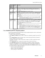
7.17.2 Configuring alarms
Perform the following steps to configure an alarm
1
Click the
Alarms
tab.
2
In the
Condition Description
column, enter a description for each condition.
The maximum length of the condition must be 32 characters. You can use special characters such as ".,/\
\<>'\"*?|:;[]{}()\ for defining the condition.
3
In the
Data Offset
column, enter the data offset byte (0 through 238) for each alarm condition. For example
if Dataoffset = 5, then parsing needs to be started from 5th byte of extended diagnostic data. The value 255
means that the data offset is not defined. Values 238 through 254 are not useful to data offset because they
do not match with any extended diagnostic data. However, having value 238 through 254 does not cause any
errors.
4
In the
Indication Bit
column, enter the indication bit (0 through 7) from where multibit processing needs to
be performed for each alarm condition.Value n = Bit n in byte represented by data offset. For example if
parsing needs to be started from bit 3 of byte 5 of extended diagnostic data, then DataOffset = 5 and Bit
offset = 3.
5
In the
Indication Bit Field
column, enter the number of bits that you want to parse from this bit. By default,
this parameter value is 1 and the maximum value that can be entered for this parameter is 32. By the virtue
of value entered in this field, you can have single bit, multi bit, and multi byte parsing of extended
diagnostic data for value. For example,
• Single bit processing: If you want to process single bit of extended diagnostic for alarming, then the
value of the Indication Bit Field = 1. If you want to process 3rd bit of 5th byte in extended diagnostic
data, then DataOffset = 5, Indication bit = 3, Indication Bit Filed =1.
• Multi bit processing: If you want to process multi bit of extended diagnostic data, then the value of the
Indication Bit Field must be greater than 1. If you want to parse from bit number 3 to bit number 5 of 5th
byte in extended diagnostic data, then DataOffset = 5, Indication Bit = 3 and Indication Bit Field = 3.
Indication bit 3 and bit field 3 means starting bit 3, 3 bits (bit 3, bit 4 and bit 5) will be parsed for value.
• Multi Byte processing: If you want to parse 32 bits starting bit number 4 of 5th byte of extended
diagnostic, then DataOffset = 5, Indication Bit = 4, and Indiciation Bit Field = 32.
6
In the
Comparison Operator
column, select the comparison operator with which you want to compare the
data offset value and the reference value. Default value of this parameter is “Equals.”
7
In the
Reference Value
column, enter a value that you want to have as a reference value for comparison.
Default value of this parameter is 1.
8
In the
User Condition PDC
column, enter the PDC number that you want to set the status based on the
alarm condition. This parameter defines whether one/none/all PDCs will be affected when a configured user-
defined alarm is active. Default value of this parameter is 255. The possible values of this parameter are as
follows:
• 254 - This means all PDCs in the DSB will be affected when this user configurable alarm is active.
• 255 - This means none of the PDCs in the DSB will be affected when this user configurable alarm is
active.
• 0.. MAXPDCNUMBER - In this case, this parameter holds a valid PDC number. The PDC number
mentioned will get affected when configured alarm is active.
Attention
For GENDSB migrated from R400 to R410, the value of this parameter is 255.
7 DEVICE SUPPORT BLOCK (DSB)
169
Summary of Contents for Experion PKS
Page 1: ...Experion PKS PROFIBUS Gateway Module User s Guide EPDOC XX88 en 431E June 2018 Release 431 ...
Page 8: ...CONTENTS 8 www honeywell com ...
Page 10: ...1 ABOUT THIS GUIDE 10 www honeywell com ...
Page 32: ...4 PROFIBUS GATEWAY MODULE PGM INSTALLATION 32 www honeywell com ...
Page 58: ...5 PROFIBUS GATEWAY MODULE PGM BLOCK 58 www honeywell com ...
Page 69: ...6 PROTOCOL BLOCK 69 ...
Page 103: ...5 Click OK 6 PROTOCOL BLOCK 103 ...
Page 110: ...6 PROTOCOL BLOCK 110 www honeywell com ...
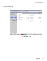
Page 183: ...PDC Details tab Figure 6 Detail Display of PDC Details tab 7 DEVICE SUPPORT BLOCK DSB 183 ...
Page 186: ...7 DEVICE SUPPORT BLOCK DSB 186 www honeywell com ...
Page 231: ...9 PROFIBUS I O MODULE PIOMB FUNCTION BLOCK 231 ...
Page 232: ...9 PROFIBUS I O MODULE PIOMB FUNCTION BLOCK 232 www honeywell com ...
Page 236: ...10 PROFIBUS GATEWAY MODULE PGM CONFIGURATION EXAMPLE 236 www honeywell com ...
Page 264: ...13 PROFIBUS GATEWAY MODULE PGM TROUBLESHOOTING 264 www honeywell com ...


