


RMA805 Enraf FlexLine Remote Indicator Quick Start Guide
3
Jumper Settings
On the Remote Indicator there is a failsafe jumper and a write protect jumper behind the
display on the Communication Module. The top jumper is the failsafe jumper. It is highly
recommended to put the failsafe jumper to DOWN (Downscale). The bottom jumper sets
the write protect.
ATTENTION:
Electrostatic Discharge (ESD) hazards. Observe
precautions for handling electrostatic sensitive devices.
Step
Action
1
Ensure the Enraf FlexLine Gauge is switched off or that the Remote
Indicator is disconnected.
2
Loosen the end-cap lock, and unscrew the end cap from the
Electronics side of the Transmitter housing.
3
Carefully depress the tabs on the sides of the Display Module and pull
it off.
4
Set the write protect jumper and the failsafe jumper to the desired
behavior. See Table 1 for jumper positioning.
5
Reinstall the Display Module. Carefully line up the display and
interface connector and snap it into place. Verify that the two tabs on
the sides of the display latch.
6
Screw on the end cap and tighten the end-cap lock.
7
Reconnect the Remote Indicator or switch on the Enraf FlexLine
Gauge.
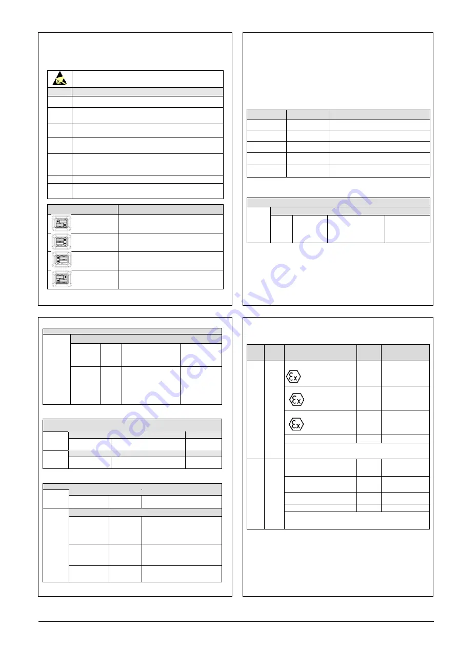
Image
Description
Failsafe = DOWN (3.8mA)
Write Protect = OFF (Not Protected)
Failsafe = UP (21.8mA) NOT RECOMMEND
Write Protect = OFF (Not Protected)
Failsafe = DOWN (3.8mA)
Write Protect = ON (Protected)
Failsafe = UP (21.8mA) NOT RECOMMEND
Write Protect = ON (Protected)
Table 1: Jumper settings
Configuration Guide
The Remote Indicator 3-button interface provides user interface and operation capability
without opening the Remote Indicator.
The user must press
↵
button to call up the Main Menu. To exit the Main Menu and
return to the PV display screen, select <EXIT>.
Use the
button to scroll through the list of menu items. Press the
↵
button to select an
item for data entry or activation. When an item is selected for data entry or activation, the
cursor is positioned over the left-most digit to allow editing of the value. No action is
taken against a menu item until the
↵
button is pressed.
Table 2: Main Menu Structure
Table 3: Display Setup Menu
Level 1
Level 2
Level 3
<Exit>
n/a
n/a
Diagnostics
Critical
Non-Critical
For details see table 6
Display Setup
LCD Contrast
For details see table 5
Device Setup
HART Setup
Parameters
For details see table 4
Information
Display
Comm Module
For details see table 3
<Return>
Return to the Level 1 menu
LCD
Contrast
<Return>
Set
Contrast
0 – 9
Default: 5
Adjust the LCD contrast
level.
Press
↵
to edit,
↑
or
↓
to select
number and
↵
to
enter.
<Return>
Return to the Level 1 menu
<Return>
Parameters
HART
Address
7 or 8
Default:
7
HART polling address
Press
↵
to edit,
↑
or
↓
to select
number and
↵
to
enter.
Standby
Time
0 – 15
Default:
5
Enter the time in minutes
until the device
automatically goes online
once in standby.
0 means the device does
NOT automatically go
online.
Press
↵
to edit,
↑
or
↓
to select
number and
↵
to
enter.
Table 4: Device Setup Menu
<Return>
Return to the level 1 menu
Display
<Return>
Firmware Version
The firmware version of the
Display Module
Read Only
Comm
Module
<Return>
Firmware Version
The firmware version of the
Communication Module
Read Only
Table 5: Information Menu
<Return>
Return to the Level 1 menu
Critical
<Return>
Comm Module
OK
FAULT
FAULT: There is a problem with the
Communications Module.
Non-
Critical
<Return>
Supply Voltage
OK
LOW
HIGH
LOW: Supply voltage is below the
low specification limit
HIGH: Supply voltage is above the
high specification limit.
Comm Module
Temp
OK
OVER TEMP
OVER TEMP: Communications
Module temperature is greater than
85°C.
Display Setup
OK
NVM
CORRUPT
NVM CORRUPT: The Display setup
memory is corrupted.
Table 6: Diagnostic Menu
All Diagnostics menu items are Read Only
Appendix A. PRODUCT CERTIFICATIONS
A1. Hazardous Locations Certifications
MSG
CODE AGENCY TYPE OF PROTECTION
Electrical
Parameters Ambient Temperature
C
ATEX
Flame-proof and Dust:
II 2 G Ex db IIC T6..T5 Gb
II 2 D Ex tb IIIC T 95°C Db
Note 1
T6: -20°C to 65°C T95°C,
T5: -20°C to 85°C
Intrinsically Safe:
II 1 G Ex ia IIC T4 Ga
Note 2
-20°C to 70°C
Non-Incendive
II 3 G Ex ec IIC T4 Gc
Note 1
-20°C to 85°C
Enclosure: Type IP66/IP67
ALL
ALL
STANDARDS: EN 60079-0: 2018; EN 60079-1: 2014; EN 60079-11: 2012; EN
60079-31: 2014; EN 60079-7: 2015;
D
IECEx
Flame-proof:
Ex db IIC T6..T5 Gb
Ex tb IIIC T 95°C Db
Note 1
T6: -20°C to 65°C T95°C,
T5: -20°C to 85°C
Intrinsically Safe:
Ex ia IIC T4 Ga
Note 2
-20°C to 70°C
Non-Incendive
Ex ec IIC T4 Gc
Note 1
-20°C to 85°C
Enclosure: IP66/ IP67
ALL
ALL
STANDARDS: IEC 60079-0: 2017 IEC 60079-1: 2014;
IEC 60079-11: 2011; IEC 60079-7: 2017; IEC 60079-31: 2013


