


49
output can be configured via ControlEdge Builder.
8.
Select the corresponding channel, and configure parameters.
Configuring serial modules
The section introduces how to add and configure a serial
communication module. Up to six serial modules can be added.
1.
From the Home Page, under
I/O and Communications
, click
Configure Modules
>
Configure Serial Modules
.
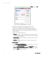
2.
Click
Add Serial Module
, the
Add Serial Module
dialog appears.
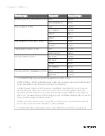
3.
Select the
Type
, assign the
Rack
and
Slot
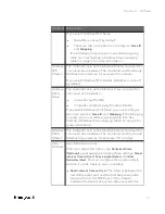
for the module.
See the following table for the parameter descriptions:
Parameter Description
Type
Serial module type: 900ES1: Serial Comm
Rack
Rack address:
l
If controller redundancy is enabled, the rack
address range is from 1 to 99.
l
If controller redundancy is disabled, the rack
address range is from 0 to 99. 0 is only for the
local I/O rack.
l
For an expansion I/O rack, the address must be
the same with the EPM address configured on
1x and 10x rotary switches.
For details about the rotary switches, see
“Assembling I/O racks” in the
ControlEdge 900
Controller Hardware Planning and Installation
Guide
.
Slot
Slot number: the location of the I/O module mounted
in the rack
l
If the I/O module is installed in a 4-slot rack, the
slot number is ranging from 1 to 4.
l
If the I/O module is installed in an 8-slot rack,
the slot number is ranging from 1 to 8.
l
If the I/O module is installed in a 12-slot rack,
the slot number is ranging from 1 to 12.
Chapter 4 - Software
Summary of Contents for ControlEdge 2020 SC-TEPL01
Page 28: ...Figure 3 8 Single star topology 28 Chapter 3 Hardware ...
Page 40: ...40 Chapter 3 Hardware ...
Page 66: ...66 Chapter 4 Software ...
Page 114: ...114 Chapter 6 Communication ...
Page 126: ...126 Notices ...