


CPO-PC400-W/CPO-PC400-UW HVAC CONTROLLER
7
EN0B-0085 IE10 R0420
General Information on the RS485
Standard
According to the RS485 standard (TIA/EIA-485: “Electrical
Characteristics of Generators and Receivers for Use in
Balanced Digital Multipoint Systems”), only one driver
communicating via an RS485 interface may transmit data
at a time. Further, according to U.L. requirements, each
RS485 interface may be loaded with a max. of 32 unit
loads.
BACnet MSTP connections to the RS485 interfaces must
comply with the aforementioned RS485 standard. Thus, it
is recommended that each end of every communication
bus be equipped with one termination resistor having a
resistance equal to the cable impedance (90 – 120 Ohm/
0.25 – 0.5 W).
RS485 systems frequently lack a separate signal reference
wire. However, the recommended wiring is to provide a
solid signal ground (signal reference) connection in order
to ensure error-free communication between drivers and
receivers – unless all of the devices are electrically isolated
and no earth grounding exists.
Under ideal conditions, the RS485 connection can have a
max. length of 1200 meters. However, the longer the cable,
the lower the transmission rate. As a rule of thumb, the
transmission rate (in bps) multiplied by the cable length (in
meters) should not exceed 100 million. For example, a
system with a cable 1000 meters long should not be
required to transmit data at rates exceeding 100 Kbps. The
following table provides a few examples.
For information on wire gauge, max. permissible cable
length, possible shielding and grounding requirements,
and the max. number of devices which can be connected to
a bus, refer to standard EIA-485.
Ethernet Interfaces and LEDs
The two Ethernet interfaces 1 and 2 are internally
connected to a single Ethernet switch.
Both Ethernet 1 and 2 can connect the controller with
laptop/PC using Ethernet crossover cable. The user can
upload, download, and debug the controller application
using ComfortPoint
TM
Open Studio from the laptop/PC.
This connection also establishes the Internet connectivity.
They are RJ45 female interfaces, each with a yellow activity
status LED (located to the left) and a green activity LED
(located to the right). The possible behaviors and
corresponding meanings of these LEDs are explained in
the following table.
The following can be connected to these two Ethernet
interfaces:
• BACnet IP
• Web browser
Table 10. Baud rate vs. max. cable length for RS485
Baud Rate
Max. Cable Length (L)
9.6 kbps
1200 m
19.2 kbps
1200 m
*38.4 kbps
1200 m
***56 kbps
1200 m
76.8 kbps
1200 m
**115.2 kbps
800 m
* In the case of configuration of RS485 interfaces 1, 2,
and 3 of the CPO-PC400-W/CPO-PC400-UW for Field
Bus, the communication rate will be automatically set to
38.4 Kbps.
** In the case of configuration of RS485 interfaces 1, 2,
3, and 4 of the CPO-PC400-W/CPO-PC400-UW for
Panel Bus, the communication rate will be automatically
set to 115.2 Kbps.
*** In the case of configuration of RS485 interface 4 of
the CPO-PC400-W/CPO-PC400-UW for CP-IO Bus, the
communication rate will be automatically set to 56
kbps.
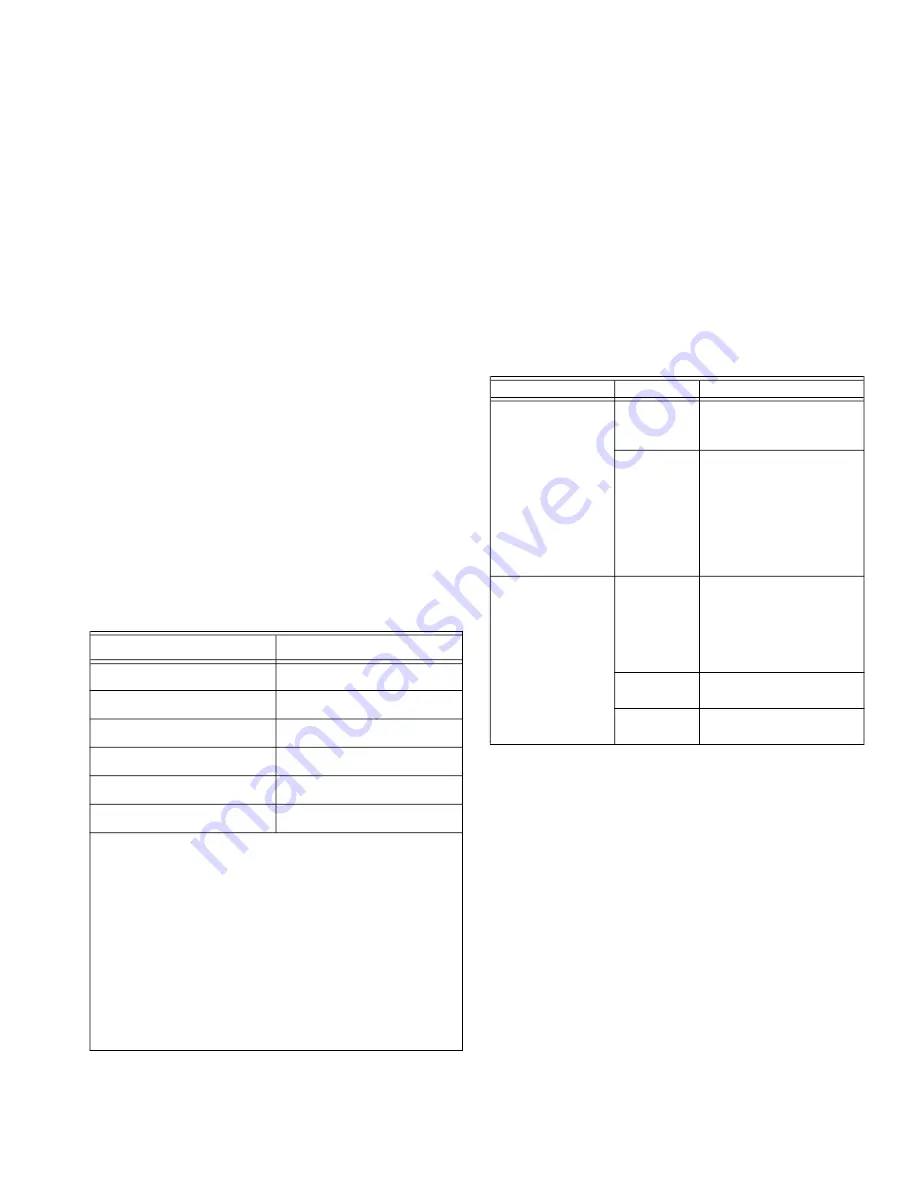
Table 11. Behavior and meaning of Ethernet Interfaces 1
and 2
LED Status
Behavior
Meaning
Yellow LED (at
left)
ON
Ethernet is working with
connectivity below 100
Mbps.
OFF
• If green LED is ON or
Flashing, then
Ethernet is working
with connectivity
below 10 Mbps
• If green LED is OFF,
then Ethernet is
disconnected
Green link status
LED (at right)
Flashing
Normal operation. The
controller is
transmitting/receiving
data
to/from the switch via
cable.
ON
Ethernet connectivity is
exist but no data flow.
OFF
No Ethernet
connectivity.