background image

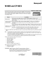
W-NXS AND CP-NXS

74-4059—01

4

Preparation

Unpack the NXS and inspect the contents of the package for damaged or missing components. If damaged, notify 
the appropriate carrier at once and return any damaged components for immediate repair or replacement—See 
“Returning a Defective Module” on page 30.
.

Included in this Package

Included in this package you should find the following items:

a NXS controller

packing slip

, which lists the factory settings for IP address, machine name, and host logon.

a hardware bag including the following:

One USB cable strain-relief bracket, with Torx T20 mounting screw.

Two panel/wall mounting brackets, with Torx T20 mounting screws.

One 2-position screw terminal plug, with locking screws, for 24Vdc power.

One 3-position screw terminal plug, for RS-485 port.

One 2-position screw terminal plug, for LON FTT-10.

Material and Tools Required

The following supplies and tools are required for installation:

a LOGO!Power 24V/4A DC power supply, DIN-mountable (included in separate package)

if a W-NXS-AX-FL or CP-NXS-AX-FL model (optional for other models), an NXS-UPS option consisting of two 
modules:

UPS module: SITOP DC-USV-Modul 15

Battery module: SITOP Power Battery 24V/1.2Ah

Inline 

fuse holder

 (Bussmann # HRF or # HMF or equivalent) 

and


compatible


4A

, 32V, fast-acting 

fuse


(Bussmann type # SFE-4 or equivalent).

Suitable enclosure for housing the NXS and other modules, as applicable. 

35mm DIN rail(s) for mounting the NXS and other modules, as the recommended method. 

Suitable tools and supplies for mounting enclosures, NXS and other modules, and for making all wiring 
terminations. 

Note

The following 

non-standard

 tools may be needed: 

Torx T20 screwdriver

, for mounting USB 

strain-relief bracket, and panel/wall mounting brackets (optional). 

Other Torx drivers (T8, 

T10)

 may be needed later if performing maintenance, and covers must be removed.

Precautions

This document uses the following warning and caution conventions:

Caution

Cautions remind the reader to be careful. They alert readers to situations where there is a chance that 
the reader might perform an action that cannot be undone, might receive unexpected results, or might 
lose data. Cautions contain an explanation of why the action is potentially problematic.

Warning

Warnings alert the reader to proceed with extreme care. They alert readers to situations where 
there is a chance that the reader might do something that can result in personal injury or 
equipment damage. Warnings contain an explanation of why the action is potentially dangerous.

Summary of Contents for Comfort Point Series

Page 1: ...enance page 20 Certifications page 31 Trademarks Niagara Framework and NiagaraAX are registered trademarks of Tridium Inc SITOP is a registered trademark and LOGO is a trademark of Siemens AG Echelon LonWorks and LON are registered trademarks of the Echelon Corporation Microsoft and Windows are registered trademarks of the Microsoft Corporation Intel and Celeron are registered trademarks of the In...

Page 2: ... local desktop environment meaning the attachment of a keyboard mouse and monitor However typical Windows access is done using a Microsoft Remote Desktop client connection to the unit as all models of NXS are factory configured to support this For related details see Local Console page 10 Table 1 W NXS features and options Model Description Ports Notes W NXS all and CP NXS all Any model NXS includ...

Page 3: ...Layout of NXS features Top 10 35 263 mm 5 24 133mm 0 39 10 mm 1 83 46 5 mm 2 7 68 5 mm 0 87 22 0 mm 5 6 142 mm 4 6 116 8 mm Front connectors Side NOTE For dimensions with wall mounting brackets installed see Figure 8 on page 10 Top frame holds LON and RS 485 Cover Plate for CompactFlash module Status LEDs See Status LEDs page 19 Connector Ports See Figure 9 on page 11 for more details Reset Button...

Page 4: ...tery module SITOP Power Battery 24V 1 2Ah Inline fuse holder Bussmann HRF or HMF or equivalent and compatible 4A 32V fast acting fuse Bussmann type SFE 4 or equivalent Suitable enclosure for housing the NXS and other modules as applicable 35mm DIN rail s for mounting the NXS and other modules as the recommended method Suitable tools and supplies for mounting enclosures NXS and other modules and fo...

Page 5: ...d control device To prevent data loss or equipment damage do not use it for any other purpose Static Discharge Precautions Static charges produce voltages high enough to damage electronic components The microprocessors and associated circuitry within a NXS controller are sensitive to static discharge The following items are cautionary notes that will help prevent equipment damage or loss of data c...

Page 6: ...imum clearance of 3 94 100mm is required around all four sides of the NXS between any other devices and or sides of the enclosure See Space Requirements page 7 Mounting orientation is strongly recommended to be horizontal only with connectors at bottom to maximize heat dissipation The following sections provide more details USB Strain Relief Space Requirements DIN Rail Mounting Wall Mounting USB S...

Page 7: ...S Power Supply SITOP UPS Battery Width minimum 27 6 701 mm 501 mm total device width plus 100 mm each side of NXS Height minimum 13 1 333 mm 133 mm device height plus 100 mm above and below NXS 3 94 100 mm minimum or more if possible 3 94 100mm min 3 94 100mm min 3 86 98 mm 3 54 90 mm 2 0 51 mm 3 94 100 mm min 5 24 133mm 10 35 263 mm NXS Power Supply SITOP UPS Battery Width minimum 22 1 561 mm NXS...

Page 8: ...lting to hook clamps over the top edge of the rail Figure 7 Step 2 Swing the device down fully onto the DIN rail until both clamps completely latch Step 3 Mount other modules Power Supply NXS UPS Battery onto DIN rail in the same fashion see the installation document shipped with each module for complete details Step 4 If needed secure devices with DIN rail end clips provided by the DIN rail vendo...

Page 9: ...provides step by step instructions for installing the brackets Procedure 2 To replace DIN mount clamps with wall mount brackets Step 1 At the back of the unit remove the four screws A securing the two DIN brackets as shown below Step 2 Install the wall mount brackets using the supplied pan head screws into the mounting holes using four screws in each bracket as shown below Step 3 See Figure 8 for ...

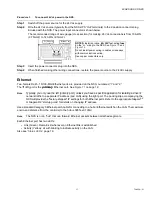
Page 10: ...g the Microsoft Remote Desktop software However in some cases you may need a local console attached to the NXS that is a keyboard mouse and monitor One example is after replacing the backup battery to re enter the BIOS setup data that was lost Note that access of the BIOS setup of a NXS is not possible over a network connection Please note the following about using a local console with the NXS A U...

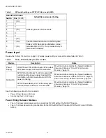
Page 11: ...kup operation during AC power outages the SITOP DC USV Modul 15 UPS and SITOP battery module See the Power Input section on page 14 4 Connect the Ethernet cable The NXS provides two 2 auto sensing 10BASE T or 100BASE TX RJ 45 connectors Use the left RJ 45 connector as the primary port see Figure 9 Make this connection to your LAN local area network 5 Other connectors include an RS 232 serial port ...

Page 12: ...to 100 mA 0 1A Ports 3 and 4 are high current ports capable of supplying up to 500 mA 0 5A Figure 11 USB Ethernet and RS 485 ports The typical application for a USB port is for communications to a NXS UPS See the USB to NXS UPS section on page 13 USB ports can also be used with a USB type PC keyboard and PC mouse if a local console is needed Note that the NXS must be rebooted after attaching a PC ...

Page 13: ...agara software See Figure 12 and Table 2 Figure 12 USB to NXS UPS connections Table 2 DIP switch settings on SITOP UPS for use with NXS NXS UPS DIP Switch Default Recommended Setting Switch Pos 0 Off 1 0 Cut in threshold is 22 5 volts 2 0 3 1 On 4 0 End of charge voltage is 27 0 volts 5 0 6 1 On 7 0 8 1 On 9 0 10 0 Charging current is 0 7A L M L M B B In Out Bat L M L 1 2 3 4 5 6 7 8 9 10 1 2 3 4 ...

Page 14: ...to disconnect the battery Table 3 Power UPS and battery modules for NXS Module Description Notes Power Supply LOGO Power 100 240Vac input 24Vdc output 90W power supply module DIN mountable Mount and wire according to shipped installation document Also see Power Wiring Between Modules page 14 NXS UPS SITOP DC USV Modul 15 24Vdc output UPS uninterruptable power supply module DIN mountable with commu...

Page 15: ... AWG 2 5mm2 Do not install power wiring in cables or raceways with communications wiring Use copper conductors only Fuse 4A 32V see Material and Tools Required page 4 L M L M B B In Out Bat L N L M Power Supply NXS SITOP Battery SITOP UPS 100 240VAC Line Neutral 24Vdc NOTES The recommended range of wire gauge cross section for making 24 Vdc connections is from 18 AWG 0 75mm2 to 14 AWG 2 5mm2 Do no...

Page 16: ...ther cases in accordance with IEC EN DIN EN 60950 1 it is necessary to use either a power source of limited performance LPS Low Power Source or use a line side fuse or line side power switch Power needs to be limited to less than 8 A The recommended fuse rating is 4 A For operation in closed cabinets or fireproofing cabinets including the operation of a cabinet in accordance with UL508 there are n...

Page 17: ...a specific application for isolating a driver s network traffic to a separate IP address and LAN using the right port The packing slip accompanying the NXS will provide the factory shipped IP settings for both Ethernet ports Refer to the appropriate NiagaraAX or Niagara R2 startup guide for details on changing IP address Use a standard Category 5 Ethernet patch cable for connecting to a hub or Eth...

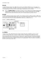
Page 18: ...screw terminal connector and always operates as COM2 Wire to this connector with shielded 18 22AWG wiring refer to the TIA EIA 485 standard As shown in Figure 15 the RS 485 screw terminals from left to right are shield GND Data plus and Data minus Figure 15 RS 485 port COM2 pinouts LonWorks A single two pin male LonWorks FTT 10A connector port and wiring plug is available see Figure 15 This connec...

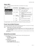
Page 19: ...ver a LAN using a networked Windows PC and a Remote Desktop Connection Windows Terminal Services Related Documentation For more information on configuring and using the NXS controller consult the following documents NXS with NiagaraAX NXS Install and Startup Guide NiagaraAX Platform User Guide NiagaraAX User Guide NXS with Niagara R2 NXS Install and Startup Guide Using the Niagara Admin Tool Niaga...

Page 20: ...device front panel page 20 Replacing the backup battery page 21 BIOS Setup page 22 Removing installing a CompactFlash card page 25 Replacing the SDRAM memory module page 27 Replacing the LON option board page 28 Replacing the hard disk page 29 Open the device front panel Caution The NXS contains electronic components that are vulnerable to static discharge Therefore take precautionary measures bef...

Page 21: ...e manufacturer Depleted batteries must be disposed of in accordance to local regulations Procedure 5 To replace the backup battery Step 1 Run BIOS setup on the NXS recording the current settings Power the unit off when done Step 2 Open the device front panel Step 3 Pull out the battery plug see below Step 4 Carefully bend up the battery strap and remove the battery Step 5 Insert the new battery in...

Page 22: ...Power saving functions are set here Boot Boot priority is set here Version Provides technical data about versions of BIOS boards firmware and hardware Exit Used to save and terminate BIOS Setup Step 6 Use the keyboard cursor keys left and right to move between menu categories and the keyboard cursor keys up and down to move between fields Other Item Specific Help is displayed in the right side of ...

Page 23: ...onnection System Date MM DD YYYY Primary Master 40008 MB 1024 MB if CompactFlash model or nnnn MB reflects hard drive size where Type Auto Primary Slave None Default None Secondary Master 512 MB None Memory Cache Write Back Default Write Back Boot options Quick Boot Mode Enabled Defaults SETUP prompt Enabled POST errors All but not keyboard Summary screen Disabled Keyboard Features Num Lock Auto D...

Page 24: ...h PCI Device Slot 3 Option Rom Scan Enabled Enable Master Enabled Latency Timer 0040h PCI Device Slot 4 Option Rom Scan Enabled Enable Master Enabled Latency Timer 0040h PCI PNP ISA IRQ Resource Exclusion IRQ 3 Available IRQ 4 Available IRQ 5 Available Reserved IRQ 7 Available Defaults IRQ 9 Available IRQ 10 Reserved IRQ 11 Reserved PCI IRQ line 1 Auto Select PCI IRQ line 2 Auto Select PCI IRQ lin...

Page 25: ... components that are vulnerable to static discharge Therefore take precautionary measures before working with it See Static Discharge Precautions page 5 Security Supervisor Password Is Disabled Defaults User Password Is Disabled Set Supervisor Password Enter Set User Password Enter Password on boot Disabled Fixed disk boot sector Normal Virus check reminder Disabled System backup reminder Disabled...

Page 26: ...push in the Eject Button then pull out the card Step 3 To install a CompactFlash card insert the card s connector side into the slot with the card s upper side facing the front panel of the NXS see below until the card locks into place Caution The CompactFlash slot is machined to prevent reversed insertion never force the card If it meets resistance flip it over and reinsert the card Card Slot Are...

Page 27: ... its pins are freed from the PC 104 connector on the bottom board Step 4 Carefully place the LON board to the side do not stress the cable to the LON connector port Step 5 Locate the SDRAM memory module on the main board as shown below Step 6 Spread open the module clamps and tilt the memory module forward Step 7 Carefully remove the memory module Step 8 Set the new memory module in the module slo...

Page 28: ...r nut driver Set the screws aside for reuse Step 4 With fingers under both edges of the LON option board near the PC 104 connector carefully lift up the board until its pins are freed from the PC 104 connector on the bottom board Step 5 Install the new LON board including the four hex screws that secure it Note Make sure that the LON board is seated correctly in the PC 104 connector The four mount...

Page 29: ... 8 screws that fasten the upper metal cover see below Set screws aside Step 2 Unplug the connector plug from the socket Step 3 Remove the four screws holding the hard disk to the back frame of the housing Set screws aside Step 4 Carefully pull the hard disk out from the housing with cable attached Step 5 Unplug the ribbon cable from the old drive and install it on the replacement drive Step 6 Inse...

Page 30: ...ools Required section on page 4 Returning a Defective Module For proper credit on the returned unit ship the defective module to Tridium within 30 days Prior to returning the unit contact one of the following Tridium offices to obtain a return authorization RA number and other instructions Please provide Product model Serial number Project currently licensed to Nature of the defect United States P...

Page 31: ...erence at his own expense Canadian Department of Communications DOC Note This digital apparatus does not exceed the Class B limits for radio noise emissions from a digital apparatus as set forth in the radio interference regulations of the Canadian Department of Communications and complies with Canadian ICES 003 Underwriters Laboratories Inc UL This device is listed for UL 916 and is also C UL lis...

Page 32: ... Honeywell International Inc Honeywell Limited Honeywell Limitée 1985 Douglas Drive North 35 Dynamic Drive Golden Valley MN 55422 Toronto Ontario M1V 4Z9 customer honeywell com U S Registered Trademark 2007 Honeywell International Inc 74 4059 01 06 07 ...

Reviews: