background image

Honeywell

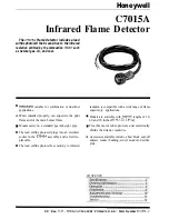
Infrared Flame Detector

The 

 Flame Detector includes a lead

sulfide photocell that is sensitive to the infrared

radiation emitted by the combustion 

 such

as natural gas, oil, and coal.

n

q

n

n

 suitable for combination or dual-fuel radiation is compatible with a wide range of flame

applications. supervisory applications.

When installed properly, can supervise the pilot

 Models are available with 

 lengths of 30,

flame and/or the main burner flame. 48 and 96 inches 


 m].

Mounts easily on a standard 

 inch sight pipe.

The lead sulfide photocell plugs into an electrical
socket in the 

 assembly and is field re-

placeable.

The lead sulfide photocell’s sensitivity to infrared

 Flexible metal cable protects and electrically

shields the detector leadwires.

q

Accessories available include a heat block, seal-off
adapter, reducer bushing, swivel mount and orifice
plate.

CONTENTS

F.P.   Rev. 

 l 

 Inc. 1991   Printed in U.S.A.   Form Number 

Summary of Contents for C7015A

Page 1: ...lot W Models are available with leadwire lengths of 30 flame and or the main burner flame 48 and 96 inches 0 76 1 22 2 64 m Mounts easily on a standard 314 inch sight pipe The lead sulfide photocell plugs into an electrical socket in the C OlSA assembly and is field re placeable The lead sulfide photocell s sensitivity to infrared W Flexible metal cable protects and electrically shields the detect...

Page 2: ...um at the lead sulfide photocell MOUNTING C7015A Mount knurled collar with 3 4 14 NPSM in ternal threads for mounting on a standard 3 4 in pipe see fig 1 104662DLeadSulfidePhotocell twoleadsforinserting into socket in C7015A see Fig 8 TABLE l MODELS AVAILABLE With 0 125 in 3 175 mm diameter hexagonal orifice to reduce the detector field of view insulate the detector from sight pipe temperatures hi...

Page 3: ...ethedetectorfromsightpipe hot gases from reaching the lead sulfide photocell 390427A Reducer Bushing to mount the detector on a temperatures higher than 125 F 52 C and up to lf2 in sight pipe specijically to replaceFireyeTM lead suljia2 infraredflame detectors Hookup Cable 250 F 121 Cl R1298020 2 wire heat and moisture resistant No 20 AWG Teflon TFE insulated ratedupto400 F 204 C for continuous du...

Page 4: ...n is the basis of a reliable flame safeguard installation Refer to the burner manufac turer instructions and instructions below Carefully follow instructions for the best possible flame detector application BASIC REQUIREMENTS Because all flames produce infrared radiation a C7015A Infrared lead sulfide Flame Detector can be used to prove the presence of a flame in a combustion chamber The detector ...

Page 5: ... length ening the sight pipe 2 reducing the diameter of the sight pipe and 3 installing an orifice plate in front of the photo cell Combinations of these methods can be used Fig P Methods of reducing C7015A Detector field of view AREA M 0 g j___ UNRESTRICTED VIEW 3 BY LENGTHENING THE SIGHT PIPE CHANGING PIPE LENGTH OR SIZE DIAMETER Theeffectorchangingthelengthofthesightpipeisshown in Tables 2 and ...

Page 6: ...75 mm diameterorifice is4in 101 6mm andfromtheorificetotheflamejunction or refractory is 36 in 914 4 mm the dieter of the sighted area is 2 4 in 70 mm Fig 3 shows how a typical orifice plate restricts the view of a small area around the flame junction TABLE ADIAMEXER OF AREA SIGHTED THROUGH ORIFICE IN IN 6 1 1 1 6 I 2 1 2 6 3 2 TABLE 5 DIAMETER OF AREA SIGHTED THROUGH ORIFICE IN MM Fig 3 4sing ori...

Page 7: ...efractory Fig 5 or at the floor of the combustion chamber Fig 6 SIGHTING SUMMARY When sighting the detector two important factors to consider are 1 proper sighting of the flame being detected normally the pilot main Rame junction and 2 avoiding hot refractory sighting A typical sighting arrangement is shown in Fig 4 The detector is aimed at the intersection of the pilot and main flames and at a re...

Page 8: ...cing a FireyeW lead sulfuie detector install a 390427 AReducer Bushing Fig 1 ORIFICE PLATE To reduce the detector field of view and restrict it to the intersection of the pilot and main flame or to a small area of hotrefractory see Fig 3 install a 105 134 Orifice Plate The or e plate can be inserted into a standard 3 4 in pipe coupling Fig 1 or into the seal off adapter if used MOUNTING SIGHT PIPE...

Page 9: ...feguardprimarycontrol oratleast 194 F 90 C if used with a flame safeguard programming control 6 For splicing in high temperature installations use Honeywell specification no R1298020 or equivalent for the F leadwire This wire is rated up to 400 F 204 Cl for continuous duty It is tested for operation up to 600 volts and breakdown up to 7500 volts For the other leadwire use moisture resistant no 14 ...

Page 10: ...ufacturer instructions or flame safeguatd control instructions Refer to Table 6 for the minimum acceptable flame currents for the amplifiers and associated flame safeguard controls With the flame detector installed and the burner running adjust the sighting position of the detector for optimum flame signal The R7748B AMRLI CHECKTM R7848A and R7848B AMPLI CHECKTM amplifiersusedwiththeBCS7700and 780...

Page 11: ...ng section Fig 12 Measuring microamp flame Signal PLUG IN FLAME SIGNAL AMPLIFIER I W136A SELECTOR TEST METER SWITCH 196146 METER CONNECTOR RED CONNECTOR CK CONNECTOR M E T E R LEAD El 208 Fig K Measuring BCS 7700 Flame Safeguard Control flame signal voltage PROBES ECS 7700 CHASSIS MODULE FOOTMOUNT E2512A Fig 14 Measuring 7800 SERIES Flame Safeguard Control flame signal voltage TABLE 6 FLAME SIGNAL...

Page 12: ...ractory reaches its maximum temperature If the installation has a multifuel burner burn the fuel most likely to reflect bend or obscure the hot refractory s steady infrared radiation burn 12 solids instead of liquids or liquids instead of gases When the maximum refractory temperature is reached close all manual fuel shutoff valves or open theelectricalcircuit of all automatic fuel valves Visually ...

Page 13: ...BLESHOOTING PROCEDURES Firstperfonn thePreliminary Inspection Then follow the applicable procedures for either a low reading or a zero reading on the flame signal meter After reinstalling the detector recheck the meter reading Adjust the position of the detector to try to obtain the proper fIame signal If the procedures are completed and a satisfactory flame signal cannot be obtained replace the d...

Page 14: ...d Checkout page 11 PERIODIC MAINTENANCE 1 Clean the focusing lens andsightpipe when necessary Remove the detector and use a soft clean cloth lhe lens does not require removal to clean it If it is broken or damaged or itiscoatedwithasubstancethatcannotbecleanedoff replace the 110634A Bushing which includes the focusing lens 2 Keep the flame detection system adjusted for the smoothest most reliable ...

Page 15: ...Flame Detector and accessories in in mm 3 Fig 2 Methods of reducing C7015A Infrared Flame Detector field of view 5 Fig 3 Using orifice plate to restrict detector field of view to intersection of pilot and main flame or to small area of hot refractory 6 Fig 4 C7015A Infrared Flame Detector aimed at side wall of combustion chamber 7 Fig 5 C7015A Infrared Flame Detector aimed at a point above refract...

Reviews: