


34
Mounting and Connection Instructions MB-Secure 4G IP USB / IP USB Extension
Module
3.4
Ethernet attachment cable
An Ethernet-type10/100BASE-T Twisted Pair cable, category 5 or higher quality
must be used. Trade name for example CB-SUTP-3; cat. 5 E; FTP; CV Cat. 5 E,
SFTP.
SUTP = Screened Unshielded Twisted Pair.
3.5
LED indicators on the Ethernet socket
LED 1 and LED 2.
There are two LEDs (left LED (yellow) and right LED (green)) on the left and
right of the RJ45 connector.
Left LED
(yellow)
Meaning
Right LED
(green)
Meaning
off
no data
off
10 Mbps
on
Data communication
on
100 Mbps
LED 3
next to the RJ45 connection indicates the transmission status of the Ethernet connection:
LED 3
(green)
Meaning
off
Half duplex
permanent
green
Full duplex
4
Installation
4.1
Installing the MB-Secure IP USB communication module
The following steps must be performed during installation:
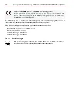
1. Remove the MB-Secure IP USB communication module from the anti-static packaging.
2. If possible, only hold the MB-Secure IP USB communication module by the edge of the cir-
cuit board.